Neurochrome Audio has a speaker protection board, one channel, which takes a large range of DC voltages for power. Neurochrome Audio

Speaker protection isn’t necessary. It often causes its own problems.
Can anyone spot speaker protection circuits in the commercial First Watt amplifiers?
Careful amplifier setup and setting of bias current will establish a safe amplifier.
Can anyone spot speaker protection circuits in the commercial First Watt amplifiers?
Careful amplifier setup and setting of bias current will establish a safe amplifier.
It seems Neutrik has become obsolete and unavailable.Heavily discussed... There are also many different types of Neutrik jacks.
^ News to me... Heck, from what I can tell they're still launching new products. I fully admit to not being 'in the know' though.
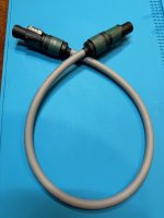
For the 4-conductor speakON (what I'm using):
These are the cable connectors
https://www.mouser.com/ProductDetail/Neutrik/NL4FXX-W-S?qs=Jm2GQyTW/bgvomtPSYACEw==
and these are the chassis connectors
https://www.mouser.com/ProductDetail/Neutrik/NL4MPXX?qs=hWgE7mdIu5T06nBoAaUABg==
These are the cable connectors
https://www.mouser.com/ProductDetail/Neutrik/NL4FXX-W-S?qs=Jm2GQyTW/bgvomtPSYACEw==
and these are the chassis connectors
https://www.mouser.com/ProductDetail/Neutrik/NL4MPXX?qs=hWgE7mdIu5T06nBoAaUABg==
All the usual sources are out or obsolete. I used to get from PartsConnexion
rdb64:
You are a genius. I looked at Mouser under Neutrik and failed. I see you searched under Connectors/ Loudspeaker.
rdb64:
You are a genius. I looked at Mouser under Neutrik and failed. I see you searched under Connectors/ Loudspeaker.
I'll have the monoblock amps built this coming weekend. (I already have built and tested F4, F5, and Aleph J amp boards.)
Here are the monoblock amps, using F4 boards. The 2 monoblocks are now working with the PSU chassis and playing music (that I'm listening to now). The capacitors are 18,000 uF (same value as used in the DC filter). All DC power wiring is 16 AWG stranded; the speaker output wiring is 18 AWG stranded; and the signal input wiring is RG-174 coaxial. Any critique or suggestions for improvement are most welcome.


GND takeout from caps to channel pcb must be in middle of that short bridge wire
route separate GND wire from back connector to each cap, so that bridge wire is not having pulsating currents, so clean GND
practically , add another white wire, leading from powercon to right cap neg, relocate white wire going to channel pcb
route separate GND wire from back connector to each cap, so that bridge wire is not having pulsating currents, so clean GND
practically , add another white wire, leading from powercon to right cap neg, relocate white wire going to channel pcb
GND takeout from caps to channel pcb must be in middle of that short bridge wire
route separate GND wire from back connector to each cap, so that bridge wire is not having pulsating currents, so clean GND
practically , add another white wire, leading from powercon to right cap neg, relocate white wire going to channel pcb

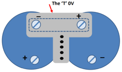
I would route the + and - supply wires from the capacitors to the white ground wire and then along it (twisted) to the board and then against the edge of the board to the connection points at the left and right. This would reduce loop areas.
Ideally, the + and - power points on the board would be co-located with the ground.
At least, that's how I would do it.
Ideally, the + and - power points on the board would be co-located with the ground.
At least, that's how I would do it.
Any suggestion on how thick the copper should be? And whether it's better to use the 101 alloy or if the 110 alloy is fine?
Doing a web search, 101 copper is oxygen free and has excellent electrical conductivity, annd has ann International Annealed Copper Standard conductivity rating of 101%. It can be easily soldered and welded. However, it is soft and difficult to machine, which means drilling or pinching holes in it will be more difficult than 110 copper.
110 copper also has good electrical conductivity at 100%+ IACS conductivity, and can be soldered to but not welded.
It seems that the decision will rest on whether you value the slight increase in conductivity that 101 copper offers, and hog you intend to fabricate and use your bus bar (eg, if you intend to punch/drill holes in the copper bus bar to attach to the capacitor terminals).
- Home
- Amplifiers
- Pass Labs
- Universal Outboard Power Chassis for Pass