
It's been a while, but I finally have the PSU 99% finished. I had another project that got in the way. I also finally got around to doing at least one hopefully meaningful measurement of it. I am still learning measurements.
It's hooked up to the A60, and I love it.
The measurement was done connected to the amp under power with no signal and an 8R dummy load. There is no noise at the speaker whatsoever.
View attachment 1215128
ItsAllinMyHead ,
This measurement is so impressive , can you review the " schematic " below to make sure its correct ?
- No EMI filter
- Dual mono supply , with one AnTek AS - 4222 toriod per supply . Which should give +/- 30 Vdc rails .
- LT4320 'ideal' rectification with Prasi's boards. No Snubber ???
- What MOSFET's were used ?
- CCLCRC filtering with the V8 boards and chokes.
- 66kuF (2x33kuF) 50V
- Hammond 159ZJ 10mH @ 5A - 0R160 series resistance
- 33kuF
- 0R165
- 33kuF
What is the bias current of an A60 Amp ? The load is an 8 resistor , but there was no signal .
People hear acoustical pressure logrithmically to the base 10 . So is the the equation for the measured noise
Noise Measurement ( dBv) = 20 log ( noise voltage / rail voltage ) .
.
Thank you. It was fun.
I think I used 4225... can't remember. My brain wants to tell me I used 4222 in my VFET and 4225 here...
Old notes show I may have used part below for LT4320.
Tried to check my Mouser order history to no avail. Prasi's got a comprehensive list of all the ones that work. I didn't pick it for any particular reason. No snubber.
Yep. All parts correct for what's in the PSU box. Not sure what exact pi resistance worked out to be. That feels correct. I think it was 2 parallel 0R33...
The Schurter PEM may have some EMI filtering, but I don't have any additional filtering. My mains is pretty clean.
There's also another... 68kuF? Elco + 2x50uF motor-run per rail in the amp chassis.
Enjoy!
I think I used 4225... can't remember. My brain wants to tell me I used 4222 in my VFET and 4225 here...
Old notes show I may have used part below for LT4320.
| CSD19501KCS |
Yep. All parts correct for what's in the PSU box. Not sure what exact pi resistance worked out to be. That feels correct. I think it was 2 parallel 0R33...
The Schurter PEM may have some EMI filtering, but I don't have any additional filtering. My mains is pretty clean.
There's also another... 68kuF? Elco + 2x50uF motor-run per rail in the amp chassis.
Best found in Randy's guide. I ran a bunch of trials. Don't remember where I landed off the top of my head. I could never match the posted specs for power output at 1% THD.What is the bias current of an A60 Amp ?
Correct. See the QA40X manual for how I did it. It was one of the first I did, so I can't claim it was done absolutely perfectly. What I do know is that it's dead silent.The load is an 8 resistor, but there was no signal .
Enjoy!
WHOOSH... over my head.People hear acoustical pressure logrithmically to the base 10 . So is the the equation for the measured noise
Noise Measurement ( dBv) = 20 log ( noise voltage / rail voltage ) .
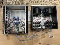
I don't really remember... I dug through the phone, and here's one while it was under construction. A lot has been tidied up since then, but it's still a work-in-progress. A buddy said he'd 3D print me a cover for the back of the PSU to hold the PowerPole connectors, but it's been fine. I added some temporary strain relief just in case it gets yanked.
I've got it set aside for the moment working on a few other things, but it will definitely get "prettied up a bit" before it goes back in the rack.
If I find some better pics on the computer later, I'll put them up.
I've got it set aside for the moment working on a few other things, but it will definitely get "prettied up a bit" before it goes back in the rack.
If I find some better pics on the computer later, I'll put them up.
Attachments
By the way, what's the rationale for adding those motor-run caps (in addition to the bulk storage caps) to the amp chassis?

Justing rationality requires understand of goals. We do it because it fills an empty chunk of chassis, especially if the caps are blue.

@rdb64 - FWIW, I had a TON of help from the two folks above + a few other people on this PSU. It's massively overkill. I nicknamed it "wretched excess". I did it for a couple reasons. #1 Fun. #2. Versatility to use it with a lot of different amplifiers (simply change out the toroids) as needed. Also, it can be two stand-alone stereo PSUs. Example - If I wanted to use that PSU to power two stereo amps for a pair of SLOBs, that's something I can do. I could use it with a BA-3 (dual mono) or a balanced BA-3. My basic goal was to have some fun. I read everything that was sent to me and then did some extra reading to try and learn about "good PSU design". I violated at least a few principles by putting in more bulk capacitance than some may recommend ... but it's DIY... After building separate PSUs to go along with almost every one of my amps, it was getting silly. So, I tried to build 'one to rule them all'.
I'm learning as I go. I have zip, zero, nada electronics background. I don't "know" anything about this. I just cut and paste notes from folks that are kind enough to help. FWIW, I found Rod Elliott's work just about right for someone like me to learn from. He has an entire section on power supply design. If you haven't seen his articles yet, I can't recommend them enough.
https://sound-au.com/articles/index.htm
My motivation and goals are almost identical to yours, though I would add learning to that list (probably at the top of the list). I actually do have the background, but it was mostly theoretical and a long long time ago. Indeed, folks on these forums have been very helpful, often providing or pointing me to the technical explanations that I'm looking for.
My key rationale was a stolen one, I steal from MZM mostly, as Serbian police have no jurisdiction in Norway.By the way, what's the rationale for adding those motor-run caps (in addition to the bulk storage caps) to the amp chassis?
Adding lower value caps at the output of the PSU, or even better: close to the load, changes the resonant frequency og the PSU. If all is done correct, a lower ESR for the higher frequencies may be achieved, in turn improving high frequency response. Does it work? I have not measured. But it sounds and looks pretty good

By the way, what's the rationale for adding those motor-run caps (in addition to the bulk storage caps) to the amp chassis?
Look at the F6 thread, post 26 by Tungsten Audio, for an explanation of how he added motor run caps and the benefits. If you search for his posts, he has used the same approach for other amp design builds.
Lots of F6 threads, but haven't yet found one with a post #26 by Tungsten Audio. Doing some more searching, but my search skills may be lacking. Haven't found it yet.
ItsAlinMyHead ,
Thanks for posting the photo of your outboard power supply .
So I take it that the measurement you took was not on a power supply rail , but rather on a speaker output .
One trick , if the noise and ripple on the +Ve rail , is equal and opposite in phase , to the noise and ripple on the -Ve rail ,
the noise gets cancelled out when Vout = 0 Vdc .
.
- Home
- Amplifiers
- Pass Labs
- Universal Outboard Power Chassis for Pass