@wcwc - I can't wait to see your build. It sounds fantastic!
I got off on a side tangent SQUIRREL / SHINY THING! I was trying to learn more about measuring PSUs independent of a signal. Fun stuff.
Anyway... I got these fun critters in the mail finally. I really wanted 'just' a covered fuse holder for more protection from mains voltage and the aforementioned verboten finger-pokin'.
https://www.amazon.com/gp/product/B075MC6W3P/ref=ppx_yo_dt_b_search_asin_title?ie=UTF8&psc=1
They're nifty. The things I did not know... or did not bother to read in advance...
1) They come preinstalled with 10A fuses. Didn't really look to see if they're fast or slow blow.
2) They have a nifty neon bulb that purportedly lights when the fuse is blown. I didn't find that in the description even after re-reading it.
3) Changing out the fuses to something more suitable isn't 'hard', but the screws are pretty tiny.
4) Easy removal/reinstallation of the fuse with the 'handle'.
5) They seem really well built.
6) I still haven't the foggiest idea what the spring-loaded clip on the base is used for... probably a standard clip in mount of some sort.
When I went to remove / change the fuse, I saw a tiny resistor... I measured it at 150k, and wondered what it could be for...
A quick Google search later revealed the neon bulb...
https://electronics.stackexchange.c...why-does-it-connect-in-parallel-with-resistor
When I install them, I'll yank the fuse and see... the light... perhaps...
If someone is looking for something similar... they get a preliminary thumbs up from me.
They will mount to this:
https://intconnector.com/products/i...g-35mm-wide-7-5mm-high?variant=40966794018968
https://intconnector.com/products/i...g-35mm-wide-7-5mm-high?variant=40966794018968

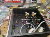
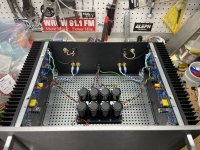
It's been a while, but I finally have the PSU 99% finished. I had another project that got in the way. I also finally got around to doing at least one hopefully meaningful measurement of it. I am still learning measurements.
@william2001 - thank you again for all the tips and advice.
There's probably a few more people that deserve direct call-outs. I posted a few things in the A60 thread and didn't want to double up. I truly appreciate everyone. If you helped ... and a lot of you did... thank you!
It's hooked up to the A60, and I love it.
The measurement was done connected to the amp under power with no signal and an 8R dummy load. There is no noise at the speaker whatsoever.
Last edited:
Pass DIY Addict
Joined 2000
Paid Member
Wow- that's one helluva nice noise profile! Congrats on a job well done!
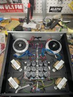
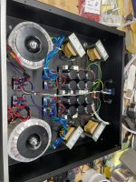
What are the specs for the big silver caps you have in the amp chassis on the previous page?
What are the specs for the big silver caps you have in the amp chassis on the previous page?
Thank you! It was a labor of love.
They're these.
https://www.digikey.com/en/products/detail/panasonic-electronic-components/DS371506-CA/821966
Edited to add - this is the profile of my "typical" CRC. Ignore all the meaningless other measurements at the top. Was learning how to add measurements to my display and graphs... Difference is that I needed to use a larger 1024 vs 128k FFT and 10 averages vs 4 to discern any of the 60 Hz peaks in the other PSU. When run like below, none of the peaks were evident. I'm not sure if that's the 'proper' way to do it or not... but... I'm learning.

They're these.
https://www.digikey.com/en/products/detail/panasonic-electronic-components/DS371506-CA/821966
Edited to add - this is the profile of my "typical" CRC. Ignore all the meaningless other measurements at the top. Was learning how to add measurements to my display and graphs...
Difference is that I needed to use a larger 1024 vs 128k FFT and 10 averages vs 4 to discern any of the 60 Hz peaks in the other PSU. When run like below, none of the peaks were evident. I'm not sure if that's the 'proper' way to do it or not... but... I'm learning.
Last edited:
Hi @ItsAllInMyHead ,
I have read individual posts, but I was only able to read through the entire development now.
It's unbelievable the energy and dedication you've invested, it's a real inspiration.
I will definitely use your experience in building "The Source Mk.II" 😀
Hats off, and thank you
I have read individual posts, but I was only able to read through the entire development now.
It's unbelievable the energy and dedication you've invested, it's a real inspiration.
I will definitely use your experience in building "The Source Mk.II" 😀
Hats off, and thank you
^ That's very kind, thank you!
Of course, as I learn more... and actually use the gear how I intended, I think of new things.
Things I have yet to do, that will be done -
1) Put my new rectification boards in and learn a little more about 'ringing'. Thanks again to those that have posted extensively about it. I haven't learned to trigger my scope properly yet to capture "just that moment". The main reason I want to continue to learn about the ringing from both the chokes and from the toroids is that I've made it very easy to swap out toroids. Even though I'm very confident that it's not a worry, I'd like to try and learn how to measure it properly in situ. Then, I can either swap in the proper resistor values for the snubber for the toroids and/or the simple resistor addition for the chokes... or just never have to worry about it again.
2) I continue to adore the PowerPole solution. Those will become part of new builds on the "amp side" also. I need to refit back panels make them more secure from a stress relief POV. Even though it's likely not necessary, I may redo the umbilicals. One, my solution isn't terribly 'clean'. Two, I am not sure if even the tiny amount of 60Hz / harmonics are from "inside" the PSU and/or if they're induced from proximity to other mains wires in the system. I'm still learning about this, but it seems that some of the "better" (I'm not talking 'audiophile') mains power cables are shielded. I may adopt that idea for the DC wiring. Someone had mentioned that "tray cable" is excellent. Using 4 individual wires for each channel that I had around seemed hasty, particularly when there seems to be purpose built wire with sheathing and shielding available at reasonable prices that I can terminate with the PowerPoles. I've gone to a lot of trouble to reduce the ripple in the PSU, it seems a shame not to do some small, but practical things to potentially keep noise from hopping onto the DC umbilical from nearby sources of radiated EMI/RFI... 🤷♂️
Things I wish I had done... but may do... kind of a pain...
- It's not directly related to the "PSU"... However, I wish I had put all the additional caps in the amp chassis on a separate base plate. Why? B/C they're not inexpensive as a unit; it seems silly to replicate it in every amp; and it's a pain to move them. I want to try this PSU with my BA-3 next. If that works well, I know I want to try it with a few others. The goal was for it to be "universal". It would be nice when changing (or even when testing) amps to:
- separate the the cap bank from the umbilical using the PowerPole 'modules'.
- separate the cap bank from the amp boards using whatever method I've built onto the amp boards. Future builds will likely all be PowerPole. Now, they're mostly FastOn type.
- Unbolt the entire "local cap" bank and pick it up as an entire unit or two units vs. 12 individual caps and plonk it into the other amp chassis. Bolt it to the base of the new chassis.
- Reattach with the "foolproof" / color coded connections into the new amp. Reattach the umbilical. Done.
- Ensure that I can safely and reliably use it as a single PSU vs. two. Possibly add another mains switch/power entry module and truly just have it as two PSUs in a box. Still debating pros and cons. Primary reason is that I have a few amps where dual mono isn't necessary / needed / desired / space requirements that I've inflicted upon myself... etc. Then there's the idea of using it for two different amps at once if I ever decide to biamp / use active crossovers etc. Just my brain running wild. It's very low on the list.
- Even though it's not related to the PSU itself... similar to #1 - have a carrier board to pop in and out of amps with speaker protection where desired.
- Possibly change soft start methodologies and have front panel switch(es) and externally visible power indicators for each PSU.
considering work to move them out, having permanently a pair of 33mF (per channel) caps inside amp chassis isn't expensive
beside, nothing ever will replace properly soldered power routes inside of amp
beside, nothing ever will replace properly soldered power routes inside of amp
^ Agreed. Love it. I'm noodling... I know that even two "connections" vs. solder isn't ideal, but I've resigned myself to the fact that I am fickle. I like to move things around.
Also, even though I'm skeptical of all marketing... The PowerPole (when used with the proper crimper) is really, really good. The mechanical connection is better than anything I've personally done... it's way better than (most of my) solder joints to things like pins on XLRs etc. So, that's my choice for things that I want to connect and disconnect until I learn of something better. With that said, I'll agree that a proper solder joint is better.
Right now... I have all the elcos and the film caps connected with wire and FastOns. Even I, the lover of all things simple, will say... that it is not 'proper'. It was easy-peasy to assemble, and manipulate the layout. I am very happy I did it this way while I was fiddling. It made it easy to move things around and add in the extra set of motor-run in parallel. However, it's likely not very good for long-term. I'm reluctant to solder until I get things 'final'.
What I'm likely going to compromise on is having PowerPole in and PowerPole out. I will find a layout that works within all the chassis, and solder all the cap connections for the "portable cap banks" with the caps on a separate small base plate(s). That's going to get rid of all the Fast-On type connections and probably about a foot of extra wire. There will still be those nasty connections from the cap bank to the PSU umbilical and from the cap bank to the amp boards. That will, in my wee brain, make the cap bank easily portable between amp chassis and remove all the "unnecessary" Fast-on type connections. Still noodling on my balance between flexibility and bullet-proof performance.
👿 <= me being stubborn imp "that just won't listen".
I started conversion of my 4U deluxe (300mm) Plethora of Pinjatas amp into a 2 box solution. Power supply will go into a 3U / 400 Pesante chassis. Setup will be dual 300va donuts, CLCRC “W12” dual mono PCB in PSU chassis to umbilical. I’m using a Hirschmann connector at the amp chassis. Amp chassis will have another dual mono CRC bank to amp boards. If I don’t like the voltage drop I can take the “2x4” CRC board to a simple a cap bank easy enough.
Eagle eyes may note the 2x4 board is not compatible with the 10x10 plate. Oops. I messed that up in KiCad. 3 drill holes and problem solved.
Thanks to @ItsAllInMyHead for some great inspiration!
I plan to convert my SissySIT chassis to use this external supply setup. Then I’ll have an extra donut and chokes for something else.
Attachments
Gorgeous!
Just had to go one up with the W12, + 8 didn't ya! I love the engine references... no replacement for displacement.
Now... I truly have not measured with or without them, and I still glaze over when I try to think of why we need "high frequency" bypass caps for a PSU... but... for not too much (relatively speaking) money ... you can put some film caps in the amp chassis. People seem to like "motor run", and I've seen some buzz lately re: "DC Link" capacitors. I can wrap my head around low output impedance for a PSU. However, for an amp that doesn't oscillate... or have feedback...I don't know what they do from a practical sense. I'd like to run some kind of test with or without to see the impact.
You likely know all that. Either way, when tapping trusted sources for building mine, there was almost universal agreement that some sort of film bypass cap was "better" even if not strictly necessary for all amplifiers.
FWIW, I don't think I've EVER gotten close to the rails with any amplifier with my speakers. So... A volt or less of drop for a prettier (even if inaudible) noise floor was a no-brainer for me. My goal was to kill the ripple, and then make real, real, real sure it was dead. Quiet enough for pre-amps if needed. Sill noodling on using 1/2 of mine for an amp and one for a pre-amp. I can measure channel separation now, and if I'm doing it properly... I'm not seeing anything meaningful with dual mono. Could be the way I'm measuring it though.
Last, but not least... thank you! again for creating the awesome boards and your thoughts around getting mine built.
Just had to go one up with the W12, + 8 didn't ya!
I love the engine references... no replacement for displacement.Now... I truly have not measured with or without them, and I still glaze over when I try to think of why we need "high frequency" bypass caps for a PSU... but... for not too much (relatively speaking) money ... you can put some film caps in the amp chassis. People seem to like "motor run", and I've seen some buzz lately re: "DC Link" capacitors. I can wrap my head around low output impedance for a PSU. However, for an amp that doesn't oscillate... or have feedback...I don't know what they do from a practical sense. I'd like to run some kind of test with or without to see the impact.
You likely know all that. Either way, when tapping trusted sources for building mine, there was almost universal agreement that some sort of film bypass cap was "better" even if not strictly necessary for all amplifiers.
FWIW, I don't think I've EVER gotten close to the rails with any amplifier with my speakers. So... A volt or less of drop for a prettier (even if inaudible) noise floor was a no-brainer for me. My goal was to kill the ripple, and then make real, real, real sure it was dead. Quiet enough for pre-amps if needed. Sill noodling on using 1/2 of mine for an amp and one for a pre-amp. I can measure channel separation now, and if I'm doing it properly... I'm not seeing anything meaningful with dual mono. Could be the way I'm measuring it though.
Last, but not least... thank you! again for creating the awesome boards and your thoughts around getting mine built.
Project completed. 22.x volts at amp rails. Perfect. Dual mono CLCRC then CRC. Bench test sounds great. Now moving to my horns. One box at a time. This must be one of the heavier 18W amps. This is the Plethora or Pinjatas SET.
Sometime in the future I’ll rip the PSU out of a similar SissySIT chassis, retrofit the back plate, and put the local cap band bank board in.
Sometime in the future I’ll rip the PSU out of a similar SissySIT chassis, retrofit the back plate, and put the local cap band bank board in.
Attachments

Cool 👍
I'm really curious whether and what differences you hear between the built-in and the separate power supply.
And your values for C and R would also be interesting (L is known), if you would share them
I'm really curious whether and what differences you hear between the built-in and the separate power supply.
And your values for C and R would also be interesting (L is known), if you would share them
Plott - My goal was lower noise on my horns. In this regard, the upgrade was a success. Before I could hear some hum from my seating position. Not anymore. It's a tough task because JBL 375 and Fostex T925A compression drivers are ~108dB eff. I was using a SissySIT with 11.5dB gain for several years. The Plethroa of Pinjatas is a 20dB gain amp so I needed to put some extra work into the power supply.
Values in this build are (same for all 4 rails):
CLCRC PSU:
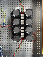
22,000uF cap
Hammond 159ZJ - 10mH @5A / 0R16 DCR
22,000uF cap
2 parallel 0R22 5W = 0R11
22,000uF cap
Amp chassis cap bank:
22,000uF cap
2 parallel 0R22 5W = 0R11
22,000uF cap
The caps, donuts, and inductors were "free" with a little labor to remove them from other chassis/boards. I picked the resistors based on values I've used on other projects and with PSUII model software. I considered higher value resistors (0R33), but with the extra RC stages it's a tradeoff between lower rail voltage and ripple.
If I were starting over I'm sure I would look at bigger caps, because that is what we do when making crazy DIY project. 33,000uF? 47,000uF?
Values in this build are (same for all 4 rails):
CLCRC PSU:
22,000uF cap
Hammond 159ZJ - 10mH @5A / 0R16 DCR
22,000uF cap
2 parallel 0R22 5W = 0R11
22,000uF cap
Amp chassis cap bank:
22,000uF cap
2 parallel 0R22 5W = 0R11
22,000uF cap
The caps, donuts, and inductors were "free" with a little labor to remove them from other chassis/boards. I picked the resistors based on values I've used on other projects and with PSUII model software. I considered higher value resistors (0R33), but with the extra RC stages it's a tradeoff between lower rail voltage and ripple.
If I were starting over I'm sure I would look at bigger caps, because that is what we do when making crazy DIY project. 33,000uF? 47,000uF?
ItsAllInMyHead ,
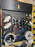
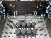
The 4 diode bridges are tie wrapped down to the chassis base .
Throwing out ideas here , consider cutting a piece of Baltic birch plywood . Then fasten the diode bridge boards to this plywood
using nylon spacers and stainless steel #4 - 40 machine screws .
For the major diameter ( outside of the threads ) of a #4 - 40 machine screw , I'm measuring 0.110 "
So if a hole was drilled 3/32 " ( 0.094" ) , then #4 - 40 machine screws should be able to self thread in to the plywood .
There are possibly better opinions for spacers , but I bought these .
https://www.mouser.ca/ProductDetail/Keystone-Electronics/878?qs=aNr0Yui8wHZFguvjmLmV1w==
Also , something to be aware of . I was prototyping an Amp with DIY CRC bench supply .
When I pushed the bias current up to 1.3 Amps the voltage drop across a 15" length of 16 or 18 awg piece of lamp cord was 10 mV .
You probably know this already , but be aware of the voltage drops across cables with these kind of currents .
I would say use 12 awg minimum .
Finally , as I've mentioned a few times , highly recommend adding a Fo Felix DIY EMI filter .
Considering the currents , a Bourns 8120 - RC could be considered for the common mode choke ... but it may need potting .
https://www.mouser.ca/datasheet/2/54/8100_series-777217.pdf
.
^ Hi @Uunderhill
Awesome recommendations/thoughts! Thank you!
Moving in order -
Thanks for taking the time for recommendations! It's still a work-in-progress.
Awesome recommendations/thoughts! Thank you!
Moving in order -
- Yeah... The tie wraps were a little embarrassing, but it got me going.
 The boards were sitting on hollow nylon standoffs that the tie-wraps went through. They're now mounted on 'swivel' PCB standoffs. They work wonderfully for boards that aren't spot on the spacing of the holes in the baseplate.
https://www.amazon.com/STARVAST-Mot...pcontext&ref_=fplfs&psc=1&smid=A1TG4XOLBU72LN
Next step, I have some purple PCBs that have the same mounting hole spacing as the base plate and have TH snubber components that I can easily change with the transformers. Just... because.
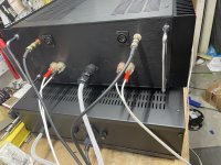
- Great to know re: the voltage drop through the umbilical. I considered it, but never gave it too much thought. The wiring is currently 16AWG. I may measure the drop just to check it out. Currently lids are actually in place. I never do that. 🙂 So, I'll check it out later. I can easily swap to 12AWG.
In practice... it's hooked back up to the Aleph 60 and playing now at ~ 2A5 Iq per channel => 2A5 per PSU. The wiring stays perfectly room temp. I'm not worried about the drop from a technical standpoint, only safety. Unless I should be worried about the actual drop??? I never come close to 'hitting the rails'. If I clip any amp, then I've done something really, really wrong. Still, it is something I should have probably given more thought. Appreciated!
- I've been lurking the Fo-Felix GB thread for ages. I might take the leap. That stuff is a mystery to me. I currently have a "medical grade" Schurter inlet module. That's being fed by some Furman unit that was given to me... which is plugged into what's for all intents and purposes a massive isolation transformer... which goes to its own breaker. I think my mains is pretty clean, but you never know... Really, I just need to learn more. My biggest concern (for the moment) is that the umbilical currently has no physical shielding and is running right behind a VERY messy rack across all kinds of other wiring. 🙂
Thanks for taking the time for recommendations! It's still a work-in-progress.
There are some very impressive projects in this thread. I have contemplated such a task for sometime acquiring a few too many boards and not enough chassis (yes, plural). There has been a discussion on the last two pages about how many cables to run in one umbilical.
My intention is to combine the two power cables for each channel with the power for the DC protection board.
Looking at some of the early schematics, there are roughly 8-9 separate conductors depending upon the grounding scheme between the two chassis.
Is there an issue with running all of this together in one rather thick cable related to electrical interference?
I see options of using 1 thick cable with both channels and the DC board power, combining the amplifier channels and having a separate DC power cable or separate cables (and jacks) for each of the power sources, as in post #25. I do realize one much consider the cost/benefit ratio of 1-3 cables and 2 to 6 jacks.
Jeffri
- Home
- Amplifiers
- Pass Labs
- Universal Outboard Power Chassis for Pass