^ I'll definitely let everyone know how it all goes and post some pics once I get things noodled through, torn apart two or three times and installed for the 'final' time.
For those that haven't already soldered everything or are planning a build ... I would give these little fellers a long hard look to see if they might work...
If I didn't cringe at the thought of taking my amp boards off the heatsinks and the filter boards off the mounts and the rectifiers... and the soft starts... and de-soldering all the blades... I sort of hope that they're a horrible, terrible, awful option... so I can put them out of my mind.

I'll definitely let everyone know how it all goes
I sort of hope that they're a horrible, terrible, awful option... so I can put them out of my mind.

Looking at those, I guess the only thing that bothers me is the tin plating. I would much prefer a silver-on-silver contact point for high current connections that rely on spring pressure. I guess my own solution would look something like: solder everything inside and have industrial connectors on the back (1st choice), or solder everything inside and have powerCONs on the back (I think Pass Labs does that?), or solder everything inside and have a short pigtail with the Powerpoles hanging out the back.. with a strain relief / grommet / etc. on the chassis.
Unsure why you are not looking at Neutrik XLR4. Rated at 10A, readily available. I use them for preamp (external psu) and they work fine.
^ I'm still considering them, but ideally (for me) I want something that does not need to be soldered. Also, the XLRs have relatively small pins that for the wire gauge I'm considering make it tough to get a nice solder joint (for me). What I really, really like is that they're easy to mount in a standard hole, and that they're properly DC rated. All previously discussed.
Edited to add - Ya know... I'm going to see if I can mock up a connector and improve my soldering skills. I have a few with solder cups instead of pins... that might make my life easier. Thanks for the reminder to keep them in the running.
Edited to add - Ya know... I'm going to see if I can mock up a connector and improve my soldering skills. I have a few with solder cups instead of pins... that might make my life easier. Thanks for the reminder to keep them in the running.
Last edited:
According to Neutrik, XLR4 max wire size is 1.5mm2 or 16AWG, so should be sufficient. For as far as I know there are crimp connectors as well, but I am unsure if the max wire size is less.
I personally hate crimping because everyone has their own specific crimping tool and they cost a fortune. Generic crimping tools often do not give great results.
XLR soldering is quite easy compared to a lot of other connectors. I bought some of the aircraft type and discarded them. Too difficult for me haha.
If you haven't soldered XLR4 before, buy some cheap ones on Aliexpress to practice/see how you go before deciding. Don't be tempted to use the cheap ones in the amp though. Some are really bad and nowhere near the rated spec of the original. Good for practicing only!
^ I totally agree re: soldering some connectors and crimping also. This is not a bash, but it is a bit of a rant, I suppose. I got some of the Cardas RCA and binding posts with the amp chassis. GOOD GRIEF! GRRRRRRR! I am 100% confident that if I knew a proper technique (tried to find references) or had a welder / blowtorch, 10,000W iron, it would be a breeze. I had to hold a 120W iron set to 750F with a chunky tip on those binding posts for what felt like an hour to get a proper bond. 🙂 The RCAs have no 'ground tab', so finding a creative way to solder that is a treat.
Just ranting in public... and agreeing with your overall premise.
Onto more productive thoughts. I just tried 16-AWG with the solder cups on some trial 3-pins (authentic Neutrik) I have around that I use for inputs. It went reasonably well. I think I can get the male-side connectors with cups also based on data sheets. I haven't the foggiest idea why I ordered parts with pins instead of solder cups for some of them... most likely just being dense and not checking the part number and assuming ...
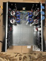
Edited to add - some fun pics for those that like pics. Not much visible progress, but a lot of nit-picky stuff done... Note... the rectifier boards will be changed to something more fun... and more usable for me in this particular supply later. Prasi is awesome!
Just ranting in public... and agreeing with your overall premise.
Onto more productive thoughts. I just tried 16-AWG with the solder cups on some trial 3-pins (authentic Neutrik) I have around that I use for inputs. It went reasonably well. I think I can get the male-side connectors with cups also based on data sheets. I haven't the foggiest idea why I ordered parts with pins instead of solder cups for some of them... most likely just being dense and not checking the part number and assuming ...
Edited to add - some fun pics for those that like pics. Not much visible progress, but a lot of nit-picky stuff done... Note... the rectifier boards will be changed to something more fun... and more usable for me in this particular supply later. Prasi is awesome!
Attachments
Last edited:
Mouser not making life any easier finding all the bits, search is dismal. No ref. to complete sets and pdf's usless.and not checking the part number and assuming ...
 Another call to mouser tech in my life.
I got a few of the Powerpole connectors to try out...
I really like them...
I'm not saying that they're better than other solutions, but I can see myself using them. If I don't use them here, then I'll almost definitely try them for single-wire connections inside a chassis to make for speedy removal and swapping of amp boards. They definitely give me a level of confidence over-and-above typical spades. Whether that confidence is merited... who knows?
Everything is relative to other solutions, and some other solutions may cover a lot of the same bases ... but... here's how I see it (for now).
Pros -
I put together a keyed / color coded pair of connectors in < 5 mins.
Thanks again to everyone for bringing these and many other solutions to the table.

I really like them...
I'm not saying that they're better than other solutions, but I can see myself using them. If I don't use them here, then I'll almost definitely try them for single-wire connections inside a chassis to make for speedy removal and swapping of amp boards. They definitely give me a level of confidence over-and-above typical spades. Whether that confidence is merited... who knows?
Everything is relative to other solutions, and some other solutions may cover a lot of the same bases ... but... here's how I see it (for now).
Pros -
- Relative to some solutions ... inexpensive, but more expensive than a pile of spades.
- Versatile / Very easy to configure. Maybe the most versatile solution I've seen. You can build your own assembly of up to X wires vs. a pre-chosen number. This, to me may be one of its biggest advantages for an assembly / umbilical. Note... mine did take a bit of percussive maintenance to get them to fully align. The reusable /interchangeable housings are great! Want to use all black wiring and only color code the housings ... nice! I color code all my wiring inside the chassis... but maybe not in the future. Want V+ to be red instead of blue... easy, just change the housing.
- Color-coded and 'pretty'. If one wants, and if one typically uses the same wire gauges and colors for particular uses, and if one already has a bunch of amplifiers built with that color coding... it would be relatively simple to match the connectors to your choice of wire (within limits). It could be for for ease-of-use / idiot proofing and/or aesthetics.
- No soldered connections. To me this is a huge pro, but ... only if I assume that the connection is 'as-good' as a soldered connection or better than Fast-on / blade types. The documentation claims better / lower resistance, and recommends not soldering them... who knows?
- Better locking force than Fast-on / blade types (based on a completely unscientific tug test)
- All parts are both male and female, but ... a keyed connector can be assembled to ensure no cross-wiring if two or more wires are used in an assembly. No more running out of male or female connectors.
- Not a 'standard' shape to work around for a chassis mount solution.
- Maybe not as good as a soldered connection?
- Special crimping tool. I have a very, very similar one, so...
- Size - for cramped spaces, they may not work. They're a bit larger than a blade-type connector, and they need a bit of room to connect / disconnect relative to other solutions.
I put together a keyed / color coded pair of connectors in < 5 mins.
Thanks again to everyone for bringing these and many other solutions to the table.
Now that's sitting on the fence with conviction...I know... make a decision already...
PowerPole inside, Neutrik outside???^ I am considering that heavily... along with... something I had typed before, but removed lest I be mocked for overcomplicating things...
<girding my loins>
Powerpole both internally and externally on the PSU side. For now, just external b/c the thought of desoldering all those connections and replacing them makes me want to vomit.
4-Pin XLR on the amp side externally and Powerpole internally (again... if I decide to de-solder the internals and replace spades / blades).
Since ... 4 pin XLR is used for other things, and I have 4-pin XLR connectors running about in the house... some mini and some standard...
With an umbilical with Powerpole on one end and XLR on the other... there is no way even a dolt like me could ever get it backwards or anyone else could ever get it wrong either...
My wife just muttered... "hold my beer"...
makes me want to vomit.
You are my canary in the coalmine. Why you need that beer. Clears vomit palete.4-Pin XLR on the amp side externally and Powerpole internally (again... if I decide to de-solder the internals and replace spades / blades).

As you have said before, just leave it and build another Pass Amp!desoldering all those connections and replacing them

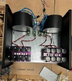
I had originally planned to do the power in a separate enclosure, but decided on what I thought would be a cleaner approach. Power supply will be mounted on a baseplate which can be swapped out or changed depending on the amp board requirements.
I am going to use amass RC connectors for all the quick connect wiring between the power supply baseplate transformer primaries to the soft start and the DC dual rail to the amp board with different connectors. Also have connectors for the amp speaker outputs and the signal inputs. All the speaker protection, soft starts, and SE/XLR converter boards are mounted to the back panel. I intend to swap out heat sinks with amp boards attached with just a few quick connections. Faceplate label will be switchable to indicate which amp is playing.
I am going to use amass RC connectors for all the quick connect wiring between the power supply baseplate transformer primaries to the soft start and the DC dual rail to the amp board with different connectors. Also have connectors for the amp speaker outputs and the signal inputs. All the speaker protection, soft starts, and SE/XLR converter boards are mounted to the back panel. I intend to swap out heat sinks with amp boards attached with just a few quick connections. Faceplate label will be switchable to indicate which amp is playing.
Can you do that on LCD panel?Faceplate label will be switchable to indicate which amp is playing.
Could probably do an LCD Panel, but I have a steel panel against the amp with a wood front out facing. Will use magnets with the wood panels to change the panels or half panels.
All that work deserves switchable LCD panel??? Dependant on amp. Not that magnets are not interesting.Could probably do an LCD Panel
Build 2!
- Home
- Amplifiers
- Pass Labs
- Universal Outboard Power Chassis for Pass