Wrong - you don't want chassis ground (ie. mains earth) to connect to signal ground ... which is the central ground star.
Andy
However, there are many double-insulated commercial equipment, and desperate audiophiles who sever the earth connection ...
How we can build a safe and earthless device?
I think that is exactly what I am doing. Two active speakerboxes which contain the powersupply plus amplifiers plus a wireless reception module each and no other connection except the mains cable.
All of this and some more in a wooden enclosure with walls of an inch thickness. So no chance of any accidental contact as long as it is closed. There is an automatic circuit for standby if no signal is received within 3 to 5 minutes , adjustable. The audio signal is received by wlan connection with a real bandwidth greater than 3000kbps (Audio) so is transmitted uncompressed and lossless. Since there is no compression transmitting and receiving the delay is minimal.The wlan itself has a bandwidth of 1200 mbit/s.
No ground connection there as its wireless so the grounding and its problems are confined to within each box alone.
No wiring at all except mains cable-
In part I am doing this just to prove I can do it , and for fun of course. I love good music and good sound.
Last edited:
Using a resistor and diodes able to large current.However, there are many double-insulated commercial equipment, and desperate audiophiles who sever the earth connection ...
How we can build a safe and earthless device?
This is not legally aprouved safety, but in fact excellent safety.
See: Earthing (Grounding) Your Hi-Fi - Tricks and Techniques
Figure 4
How we can build a safe and earthless device?
You're describing a "Class II" device. There are many requirements (from a regulatory view) to building this type of device. I suspect this is typically beyond the skill set of the typical DIYer. And from a safety perspective, most DIYers would probably advise against pursing it. Just my 2 cents.
much more. We would forget the absence of earth connection working on open box, and we would use cardboard or wood as electrical insulator.
Using a resistor and diodes able to large current.
This is not legally aprouved safety, but in fact excellent safety.
See: Earthing (Grounding) Your Hi-Fi - Tricks and Techniques
Figure 4
Excellent. Same as what Nelson Pass says.
Except, NP does not include the 100 nF cap in parallel with the resistance.
Last edited:
Preamp grounding scheme
Hello,
I would like to ask for advice if below sheme is best practice on how to do the grounding.
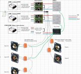
I'm doing the concept of a preamp with 3 transformers, where each xfmr has double secondary windings and where each secondary has it's own bridge rectifier. This is visible by the two black lines (0's) at the output of psu PCB.
The actual buffers (preamp without gain) will have Jung-Didden superregulators.
The grounding scheme has impact on the PCB design, which is also work in progress.
Hope the picture is clear enough for you all. At the left you can also find the earth ground loop breaker. This preamp will drive two monoblock amps.
Regards
Hello,
I would like to ask for advice if below sheme is best practice on how to do the grounding.
I'm doing the concept of a preamp with 3 transformers, where each xfmr has double secondary windings and where each secondary has it's own bridge rectifier. This is visible by the two black lines (0's) at the output of psu PCB.
The actual buffers (preamp without gain) will have Jung-Didden superregulators.
The grounding scheme has impact on the PCB design, which is also work in progress.
Hope the picture is clear enough for you all. At the left you can also find the earth ground loop breaker. This preamp will drive two monoblock amps.
Regards
Attachments
Last edited:
Each transformer/PSU should have it's own ground loop breaker.
All high impedance signal wiring should be coax and laid out with minimal loop area.
Use hum breaking resistors in your amp design.
All high impedance signal wiring should be coax and laid out with minimal loop area.
Use hum breaking resistors in your amp design.
Each transformer/PSU should have it's own ground loop breaker.
All high impedance signal wiring should be coax and laid out with minimal loop area.
Use hum breaking resistors in your amp design.
Hi Mark,
Each xfmr a ground loop breaker? This would mean there are 3 ground loop breakers in parallel, while at the end there is on star ground, not?
My amp has indeed 10R + 2 antiparallel hum breaking resistors between signal input ground and power ground.
Is the way I routed the gnd lines correct? All to start ground, made between 0V's of the two PSU's for the buffers?
Almost:
- 2x mono preamp (buffer)
- 1x transformer for all other circuits: input selection, volume control...
This preamp will drive two monoblocks.https://www.diyaudio.com/forums/sol...low-nfb-fet-front-bjt-ops-13.html#post6043036
- 2x mono preamp (buffer)
- 1x transformer for all other circuits: input selection, volume control...
This preamp will drive two monoblocks.https://www.diyaudio.com/forums/sol...low-nfb-fet-front-bjt-ops-13.html#post6043036
Is the way I routed the gnd lines correct? All to start ground, made between 0V's of the two PSU's for the buffers?
What you are calling gnd lines are signal returns and should be close coupled with signal flow (ie use coax) and go directly back to where they originated
Forget the Star idea.
Each DC supply common (aka ground) should attach to it's audio circuit common (aka ground) and both commons should attach to the chassis at a single point near that circuit's input connectors.
Each DC supply common (aka ground) should attach to it's audio circuit common (aka ground) and both commons should attach to the chassis at a single point near that circuit's input connectors.
Forget the Star idea.
Each DC supply common (aka ground) should attach to it's audio circuit common (aka ground) and both commons should attach to the chassis at a single point near that circuit's input connectors.
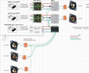
Thanks for the valuable input. I've changed the scheme.
This is as good as identical as I have done inside my monoblocks.
Any comments?
Attachments
I would route the grounds a little differently.
Do not connect the power common of each supply to the common ground buss. Rather, connect the common of each supply to the common of its load circuit.
Then connect the common of each load circuit to the common ground buss as you have shown.
This will keep the return currents from unnecessarily mixing, while still providing a common voltage reference for the circuits.
I've done some cleanup and decided to not use the same PSU for the muses 72320, logic and input selection. So I added an extra xfmr.
Each PSU goes to his load.
There is 1 audio ground start point. From wich one gnd cable leaves for all input RCA's and 1 for the two output RCA's to avoid ground loops whitin the preamp enclosure when for example a source is connected.
I'm wondering what to do with the earth loop ground breaker. It's now connected to the common of the input selection PSU? Any good?
Attachments
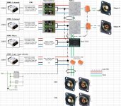

Something like this. Green is coax, all power are twisted triplets.
If you can design the switching and MUSES as two independent channels, even better.
- Home
- Amplifiers
- Power Supplies
- understanding star grounding