as well as twisting the flow and return of every pair, you must also minimise the LOOP AREA at every terminal pair connection.
It's the AREA of the gap between Flow and Return that picks up, or emits EMI.
Listening not an adequate test for amplifier output noise. Measure the Hum+Noise at the output using a voltmeter set to read at least 0.1mVac
< 0.1mVac is very good.
0.1mVac to <0.3Vac is good.
>0.3mVac of H+N is poor and can be heard with sensitive speakers and interferes with the wanted audio, even though it may not be obviously audible.
To Forr, I like your suggestion of the heatsinks in front, it makes a lot of sense and should help me improve my groundloops.
To AndrewT, I thought it was too good to be true,dang you just burst my bubble😱. I measured the voltage at the output and it is 0.06v which I assume is 60mv. I will endeavour to improve on this.
To AndrewT, I thought it was too good to be true,dang you just burst my bubble😱. I measured the voltage at the output and it is 0.06v which I assume is 60mv. I will endeavour to improve on this.
as well as twisting the flow and return of every pair, you must also minimise the LOOP AREA at every terminal pair connection.
It's the AREA of the gap between Flow and Return that picks up, or emits EMI.
Listening not an adequate test for amplifier output noise. Measure the Hum+Noise at the output using a voltmeter set to read at least 0.1mVac
< 0.1mVac is very good.
0.1mVac to <0.3Vac is good.
>0.3mVac of H+N is poor and can be heard with sensitive speakers and interferes with the wanted audio, even though it may not be obviously audible.
Hi Andrew,
A few basic questions on how to actually conduct a test like this.
- Would you have a source connected when doing this (but the source turned off). Or would you have the amplifier powered up but with input unconnected?
- When measuring for Hum+Noise at the output terminals, should a speaker or dummy load be connected?
Thanks in advance!
to check the power amplifier:
a.) remove the load/s
b.) insert zero ohms dummy plugs to all inputs
c.) power ON via a Mains Bulb Tester.
Set your DMM to 200.0Vdc
d.) measure the output offset of the power amp. If very low,
reset to 20.00Vdc and measure again. If very low, reset to 2.000Vdc, if very low reset to 200.0mVdc.
Now remove the dummy zero ohm plugs and repeat all the measurements.
An AC coupled amplifier will give the same DC results.
A DC coupled amplifier may give VERY different measurements when the source impedance is changed.
Set your DMM to 200.0Vac.
reinsert the zero ohms dummy plugs.
e.) measure the output offset of the power amp. If very low,
reset to 20.00Vac and measure again. If very low, reset to 2.000Vac, if very low reset to 200.0mVac.
f.) Swap the dummy plugs for long interconnects.
repeat all the AC measurements.
g.) short the remote ends of the long interconnects.
repeat all the AC measurements.
h.) connect the screens at the remote ends of the long interconnects.
Repeat all the AC measurements.
Expect some or a lot of variation in results from these different tests.
Last edited:
Hi Andrew
Could you please clarify a few things for me here?
1) Whats a zero ohm dummy plug?
2)By "all inputs" are you referring to the rca connectors at the rear of the case.
3)Whats output offset?
4)AC coupled / DC coupled?
5)"long interconnects" / "connect screens".
I feel like the dummy plug.
Could you please clarify a few things for me here?
1) Whats a zero ohm dummy plug?
2)By "all inputs" are you referring to the rca connectors at the rear of the case.
3)Whats output offset?
4)AC coupled / DC coupled?
5)"long interconnects" / "connect screens".
I feel like the dummy plug.
Take a cheapo (you can buy a dozen from china @ ~£2 for all 12) RCA plug and solder a copper wire from pin to barrel.
Put back on the outer cover and label it 0ohms
Make up a few.
Make up some with a resistor wired between pin and barrel. I have two each of 100r, 1k0, 10k & 100k so that I can see the effect of different source resistances/impedances on the H+N at the output.
Yes, the input sockets that feed signal into the amplifier.
A DC coupled output allows DC voltage to be applied to any load. Speakers do not tolerate high levels of DC mixed with the signal.
The DC is referred as output offset.
It is measured with the output open, using a DC voltmeter.
It must be less than 100mVdc and preferably <10mVdc for normal 8ohms speakers. Very high sensitivity may need even lower. Headphones definitely need lower.
A capacitor between a source and a receiver blocks DC and allows AC current to pass. Our audio is ONLY AC current. We don't need and don't want DC current passing from Source to Receiver.
AC coupled amplifiers have DC blocking capacitors at various locations in the signal flow to prevent damaging DC currents from flowing.
DC coupled do not have that protection and NEED other forms of detection and protection
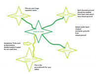
An interconnect has two wires. Usually we use coaxial cable for interconnects, the Signal current Flows from Source to Receiver along the core of the coaxial cable. That signal current MUST RETURN to the Source. It does so along the screen/shield of the coaxial cable. Thus we has a two wire connection system that carries Flow and Return current between send and receive modules.
Many around here refer to the signal return as ground. Unfortunately they also refer to a multitude of other nodes and wires and traces and terminals as ground as well. CONFUSION reigns.
Use the correct name for each return wire/trace/node and avoid the "ground confusion".
At the remote end of the interconnect you have a terminal plug that has TWO metal connectors, the core becomes pin and the screen/shield becomes barrel.
If you connect the two barrels together for a stereo amplifier it sees that connection as a loop and that loop picks up interference that eventually becomes an input to be amplified by the stereo amplifier and comes out to the speaker as interference noise. (this is what the H+N measurement reveals).
You can connect the two barrels with a crocodile clip. (you just need some interference current to flow around the loop).
This is a DIYaudio Forum that has a vast range of Members from professionals in the electronics and/or electrical fields to amateurs with a vast array of test instruments and knowledge to use them to amateurs that have never read about anything electrical and probably had little electrical education at school.
DIY includes reading about electronics. It cannot be Builders ONLY. At some stage you need to see it being done or read about how it should be done. Youtube is a valid alternative for learning.
BUT !!!!!
a big part of learning is sorting the wheat from the chaff. A lot of what appears on the internet is chaff. You have to learn to recognise it and discard it.
Put back on the outer cover and label it 0ohms
Make up a few.
Make up some with a resistor wired between pin and barrel. I have two each of 100r, 1k0, 10k & 100k so that I can see the effect of different source resistances/impedances on the H+N at the output.
Yes, the input sockets that feed signal into the amplifier.
A DC coupled output allows DC voltage to be applied to any load. Speakers do not tolerate high levels of DC mixed with the signal.
The DC is referred as output offset.
It is measured with the output open, using a DC voltmeter.
It must be less than 100mVdc and preferably <10mVdc for normal 8ohms speakers. Very high sensitivity may need even lower. Headphones definitely need lower.
A capacitor between a source and a receiver blocks DC and allows AC current to pass. Our audio is ONLY AC current. We don't need and don't want DC current passing from Source to Receiver.
AC coupled amplifiers have DC blocking capacitors at various locations in the signal flow to prevent damaging DC currents from flowing.
DC coupled do not have that protection and NEED other forms of detection and protection
An interconnect has two wires. Usually we use coaxial cable for interconnects, the Signal current Flows from Source to Receiver along the core of the coaxial cable. That signal current MUST RETURN to the Source. It does so along the screen/shield of the coaxial cable. Thus we has a two wire connection system that carries Flow and Return current between send and receive modules.
Many around here refer to the signal return as ground. Unfortunately they also refer to a multitude of other nodes and wires and traces and terminals as ground as well. CONFUSION reigns.
Use the correct name for each return wire/trace/node and avoid the "ground confusion".
At the remote end of the interconnect you have a terminal plug that has TWO metal connectors, the core becomes pin and the screen/shield becomes barrel.
If you connect the two barrels together for a stereo amplifier it sees that connection as a loop and that loop picks up interference that eventually becomes an input to be amplified by the stereo amplifier and comes out to the speaker as interference noise. (this is what the H+N measurement reveals).
You can connect the two barrels with a crocodile clip. (you just need some interference current to flow around the loop).
This is a DIYaudio Forum that has a vast range of Members from professionals in the electronics and/or electrical fields to amateurs with a vast array of test instruments and knowledge to use them to amateurs that have never read about anything electrical and probably had little electrical education at school.
DIY includes reading about electronics. It cannot be Builders ONLY. At some stage you need to see it being done or read about how it should be done. Youtube is a valid alternative for learning.
BUT !!!!!
a big part of learning is sorting the wheat from the chaff. A lot of what appears on the internet is chaff. You have to learn to recognise it and discard it.
A good aluminum heatsink has a flat surface and the thickness is 3mm or more so that makes a ground bar of 3mm times its height so say 50mm which gives a ground bar of 150 mm2 or more . Does anything speak against drilling and tapping a few holes into that below the pcbs and then using the heatsink as the central point of a ground star ? Take the central point of the power supply to that heatsink as well and it will give you the chassis ground as too as it is screwed on to that. This is assuming you have a common heatsink for the chipamps and that those are electrically isolated from the heatsink.
The bigger the heatsink the bigger the groung bar. This way there can be no ground voltages between the different amps grounds ever. Right or wrong? If wrong please explain why.
The bigger the heatsink the bigger the groung bar. This way there can be no ground voltages between the different amps grounds ever. Right or wrong? If wrong please explain why.
Last edited:
Mark Whitney has sent me this link in another thread. I found it very interesting.
Thanks Mark
https://www.updatemydynaco.com/documents/GroundingProblemsRev1p4.pdf
Thanks Mark
https://www.updatemydynaco.com/documents/GroundingProblemsRev1p4.pdf
What about the resistance of the wires? A "T" at the main smoothing caps is best and allows control of the ground currentsThe bigger the heatsink the bigger the groung bar. This way there can be no ground voltages between the different amps grounds ever. Right or wrong? If wrong please explain why.
The groundwires go from the pcbs to the heatsink so should be 2 inches or less. Cant be any shorter. Plus one can solder them to the pcb as close as possble , say from the point where de decoupling caps of the pcb are joined. The 3 wires from the caps of the power supply, ground of that and rails, can be twisted together tightly so cancel any radiation and that ground goes to the heatsink as well so we get the rails to where the pcbs without any loops too. There can , this way , be no measurable voltage differences within the heatsink and whatever difference there is in the 2 inches or so of wire connecting the ground of the pcbs in question will only affect the pcb which causes it but never the others as the heatsink which can not develop any measurable voltages within itself is the common ground then. It does not matter if there are 2 or 4 or more pcbs either. The heatsink even being aluminium instead of copper is the biggest most solid ground bar in the system and as it has to be there anyways it is a free ground bar. It doesnt cost any extra.
Last edited:
A good aluminum heatsink has a flat surface and the thickness is 3mm or more so that makes a ground bar of 3mm times its height so say 50mm which gives a ground bar of 150 mm2 or more . Does anything speak against drilling and tapping a few holes into that below the pcbs and then using the heatsink as the central point of a ground star ? Take the central point of the power supply to that heatsink as well and it will give you the chassis ground as too as it is screwed on to that. This is assuming you have a common heatsink for the chipamps and that those are electrically isolated from the heatsink.
The bigger the heatsink the bigger the groung bar. This way there can be no ground voltages between the different amps grounds ever. Right or wrong? If wrong please explain why.
You would want the heatsink to be isolated
From everything. The last piece of the puzzle is a ground loop breaker between power ground and chassis/PE.
A good aluminum heatsink has a flat surface and the thickness is 3mm or more so that makes a ground bar of 3mm times its height so say 50mm which gives a ground bar of 150 mm2 or more . Does anything speak against drilling and tapping a few holes into that below the pcbs and then using the heatsink as the central point of a ground star ? Take the central point of the power supply to that heatsink as well and it will give you the chassis ground as too as it is screwed on to that. This is assuming you have a common heatsink for the chipamps and that those are electrically isolated from the heatsink.
The bigger the heatsink the bigger the groung bar. This way there can be no ground voltages between the different amps grounds ever. Right or wrong? If wrong please explain why.
Wrong - you don't want chassis ground (ie. mains earth) to connect to signal ground ... which is the central ground star.
Andy
As a general rule the star ground (if used) should not be mounted on the chassis, although this mistake seems surprisingly popular. It may be connected to the chassis by a single wire.
A good aluminum heatsink has a flat surface and the thickness is 3mm or more so that makes a ground bar of 3mm times its height so say 50mm which gives a ground bar of 150 mm2 or more . Does anything speak against drilling and tapping a few holes into that below the pcbs and then using the heatsink as the central point of a ground star ? Take the central point of the power supply to that heatsink as well and it will give you the chassis ground as too as it is screwed on to that. This is assuming you have a common heatsink for the chipamps and that those are electrically isolated from the heatsink.
The bigger the heatsink the bigger the groung bar. This way there can be no ground voltages between the different amps grounds ever. Right or wrong? If wrong please explain why.
Attachments
I believe Douglas Self advises to connect the input ground to the chassis ground from the input connector. And then again from the input connector to the star ground. He discusses this in his "Audio Power Amplifier Design" book in chapter 25. There is a graphic of it in Figure 25.1 and a description of the rational for this in the "Amplifier Grounding" section. I am hesitant to post the graphic from the book as it is copyrighted material.
I have to give an additional explanation here.I am talking and consulting all this for a special case : I am building two active 4-way speakerboxes in which the radiator is not in any contact with a grounded casing. The whole electronics are mounted inside a wooden compartment at the base of the box which is insulated and well ventilated as well. The inside of the wooden compartment will be screened with aluminum foil but there is no metal casing as in an amplifier. In addition the signal to these boxes will be by streaming using a high bandwidth wlan connection so their only connection to the outside world will be the mains-cable
- Home
- Amplifiers
- Power Supplies
- understanding star grounding