Dear Biblio its name inspired me to think his name was linked to a book, books that philosophers love. Biblo is Latin: Book. When I saw that after confessing you was new to the subject, and watching as hard is this topic. I thought the discussion was going to take a philosophical charisma. Perhaps with the advance of the day or lately, the night, my tiredness made that he could not understand "In totto" your topic.
I apologize sincerely. Thanks for making me see my sarcasm and I've learned that patience is a gift that must recover each day. Fortunately the rest of the members of this thread have been able to handle the situation with understanding and kindness.
Best regards and welcome
I apologize sincerely. Thanks for making me see my sarcasm and I've learned that patience is a gift that must recover each day. Fortunately the rest of the members of this thread have been able to handle the situation with understanding and kindness.
Best regards and welcome
Last edited:
i'm pretty sure that my house has an earth rod as i remember seeing it when they were replacing the consumer unit. but like always i could be wrong. house was built in the 50's.
Biblio is a book term but Bibio is not, it's a trout fishing fly.
i sincerely apologise for getting the wrong end of the stick. peace my friend 🙂 xx
i sincerely apologise for getting the wrong end of the stick. peace my friend 🙂 xx
Peace in the world of Diyaudio. you welcome. I am not Spaniard. I got the citizen from Spain, I live here (peacefully, healthy and happy) in the paradise. Every year many Scottish came to take their holidays. Of course you are welcome.
An all metal water pipe system makes a much better connection to the dirt than a rod/stake ever will. In your example, it really didn't happen that way.
The problem was the water pipe running through the house did not touch the dirt except by earth wire so could float at mains if the earth wire failed.
I think all Australia now uses the MEN system which is much safer. My last house had an earth stake in the ground but it was older.
There are two things to grasp:
- flow and return, as you say - this is about currents which always need a loop
- voltage reference, as there is no such thing as "a voltage" - voltages always need a reference
Get these two clear in your mind and much of the problem disappears. Thoughts of 'ground' as some bottomless sink of current and equipotential surface then fade away, as they should.
Hello!!!
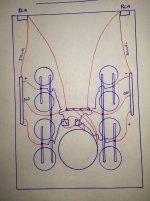
This is my latest drawing,i think i got it.
An externally hosted image should be here but it was not working when we last tested it.
Red lines are signal hot,black signal return.Lm3886 and two of 1875 are on separate borads.All signal returns are seperate on amplifier boards and then connecting together on Preamplifier board and from here go to main audio ground.Now all signals having it's own return wire close coupled.....Is this correct?
Last edited:
You also need to include the power grounds in your diagram this is where problems lie when you have multiple grounds from a single component.
You also need to include the power grounds in your diagram this is where problems lie when you have multiple grounds from a single component.
This is power and speaker grounding(top layer of the board power traces are at bottom) ignore the signal grounding they will be connected as i draw in my previous post.
An externally hosted image should be here but it was not working when we last tested it.
No, the long commoned wires to your star ground will introduce interchannel crosstalk. The important thing about a star ground should be that it is a star, not that it is ground.basi said:Is this correct?
Last edited:
Whatever i do (even if i follow what you members of Diyaudio say) is no good!!!
It's not help at all i think i should put all boards,elements and other staff to Trash and end this agony.Buy some cheap logitech speakers and enjoy in music an forget this torment...
God bless you all!!!
It's not help at all i think i should put all boards,elements and other staff to Trash and end this agony.Buy some cheap logitech speakers and enjoy in music an forget this torment...
God bless you all!!!
If EVERY circuit has close coupled Flow and Return PAIRS, them you are correct.Hello!!!
This is my latest drawing,i think i got it...................Now all signals having it's own return wire close coupled.....Is this correct?
Your drawing does NOT show close coupled PAIRS.
Up to you. You can buy stuff which works, make stuff which works, make stuff which doesn't work (or buy stuff which doesn't work).basi said:Whatever i do (even if i follow what you members of Diyaudio say) is no good!!!
It's not help at all i think i should put all boards,elements and other staff to Trash and end this agony.Buy some cheap logitech speakers and enjoy in music an forget this torment...
Audio electronics is a branch of electronics. Electronics is a branch of electrical engineering, which is a branch of applied science. Science takes time to learn; the universe is as it is, however much we may wish it were something different.
People often get grounding wrong. The usual problem is either that they don't know that there is a problem or they seek simple recipes as a substitute for understanding voltage and current.
Some simpler pictures that illustrate the current loops:
http://www.x2y.com/filters/TechDay0...log_Designs_Demand_GoodPCBLayouts _JohnWu.pdf
No point giving up at the first hurdle...
For low level analogue a ground plane is the best solution, not the spiders legs routing that many employ, these are just antennas that pick up noise and add inductance. Separating the high current speaker supply to avoid IR drops is all that is required. Keep things simple especially if you do not really understand grounding.
One technique that is not used often on audio DIY sites is pseudo balanced routing for the input signal, this if done correctly has many benefits. this technique is used in the wider world of electronic designs for sensitive analogue signals at all frequencies (audio and higher frequency analogue). Here is an older data sheet with a bit more info.
http://www.ti.com/lit/ml/sloa089/sloa089.pdf
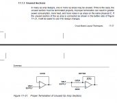
in the Ti sloa089 there is a paragraph covering loading the unused sections.
What is the difference between GOOD and BETTER?
If I implement the zero and open in the Better I end up with the same connections as in the Good.
BTW, the png attachment is ~27kB
in pdf it would be 31kB and in jpg it would be 38kB
What is the difference between GOOD and BETTER?
If I implement the zero and open in the Better I end up with the same connections as in the Good.
BTW, the png attachment is ~27kB
in pdf it would be 31kB and in jpg it would be 38kB
Attachments
Last edited:
dear dady, sarcasm is the lowest form of wit my friend and i find it strange that a Spaniard could be capable of it, but i like your style of trying. amateurs like myself struggle to understand because of people like yourself, just remember that everyone is good at something and we all need others to help.
thanks everyone. i knew i was wrong so i'll do as suggested and go looking on the net to TRY and understand a bit more.
I did not believe that he was expressing sarcasm.. The topic is indeed quite boring to most.
jn
Dobro Basi, Dude, be patient. The universe needed fithteenthousendmillonyears. The problem of ground is hard and boring.
Take you time in learn crosstalk. You not believe but this is bitter theme for everybody. Follow the instructions and not get a stupid logitech. Make your own experiments, burn pcbs and take the pulse to the electronics applied to audio. Enjoy the music is the goal.
maiko moia.
Take you time in learn crosstalk. You not believe but this is bitter theme for everybody. Follow the instructions and not get a stupid logitech. Make your own experiments, burn pcbs and take the pulse to the electronics applied to audio. Enjoy the music is the goal.
maiko moia.
Thank you
I had the patience to go through the whole thread. 😛
One of the most useful!!! Enlightening!
Saved me tons of time and trials. Thanks everybody for your contributions.
I am in the process of designing my dual mono power amp.
I’ll post the grounding/earth diagram when it’s done and tested.
Cheers
I had the patience to go through the whole thread. 😛
One of the most useful!!! Enlightening!
Saved me tons of time and trials. Thanks everybody for your contributions.
I am in the process of designing my dual mono power amp.
I’ll post the grounding/earth diagram when it’s done and tested.
Cheers

Probably an external hum loop due to mains earth. You don't show the chassis grounding and the mains protective earth grounding arrangement.
Best to make a single point connection of PT CT wires and cap 0V wires - as all the references remind you - and not spread them over a 0V busbar.
Take the amp module 0V lines to the main earth bar (not the main caps 0V).
Best to make a single point connection of PT CT wires and cap 0V wires - as all the references remind you - and not spread them over a 0V busbar.
Take the amp module 0V lines to the main earth bar (not the main caps 0V).
- Home
- Amplifiers
- Power Supplies
- understanding star grounding