now here is a problem there, virtual arc size tells the lens placement, and the lens to arc placemnt determines virtual arc size... this is like iterative problem.
Iterative problem is when you need to give one value to someting and then work out all other values and see if the first value is fine, if it is not, then change it increasing or decreasing (it depends on the last time error direction) and try again, finally you get to the result close enough.
anyway I´ll try to work out the ideal placement including arc lengh as one parameter to be considered as well. Let´s work it out 😀
An externally hosted image should be here but it was not working when we last tested it.
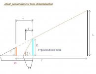
This is the problem, there are all the variables drown.
V= virtual arc half lengh.
A= real arc half lengh.
D=half precondensor lens diameter.
F=focal of precondensor lens.
d=arc--precondensor lens distance.
t=virtual arc---precondensor lens dist.
f=rear fresnell focal lengh.
L=half lcd or half rear fresnell diagonal.
The problem is to work out d and t so we know where to place the precondensor lens. The following data is supossed to be known: A, D, F, f, L.
The equations are well known also;
1/F - 1/d =-1/t
A*t/d=V
now, if you like doing maths, it is a good problem. Any interested there? 😀
You never rest mate? 🙂
Your 2 equation three variables system has no finite solution, but if your draw and mathematical statements are correct (haven't checked them myself), you can squeeze them a little more and solve the system. I've done it as you seem unable to (just guessing, you haven't proven to be lazy though far 😉). It's noted down in a hurry while cooking so I cant really swear there's no error in it, though I'll work it again tonite to be safe...
It reduces to a quadratic equation ax2+bx+c=0
x=d
a=L+D
b=f(2A-2D-L)
c=f2(D-A)
A is your "real arc halflenght", f2 is square...
I'm sure anyone can solve this basic mathematics, and perhaps there's a more fancy solution but I'm not gonna waste hours to know if there is myself.
i´ll have a look to your maths right now, but first would like to tell you there are more equations implied than what i posted (for instance you can get the relation of V and D just doing it intersect with the light tringle.)
i think i get to a solution also, but am testing it before postine here.
i think i get to a solution also, but am testing it before postine here.
there is something wrong on your math, There should be F somewhere (F= the focal lengh of precondenser lens). It is very important variable.
There are same equations as variables, this means there is only one solution for it. I think the easiest way findig the solution is the iterative way. But I think my solution is fine as well, just let me check something more before posting...
good try 😀 Rox
There are same equations as variables, this means there is only one solution for it. I think the easiest way findig the solution is the iterative way. But I think my solution is fine as well, just let me check something more before posting...
good try 😀 Rox
🙂
Quoting myself... "if your draw and mathematical statements are correct...you can squeeze them a little more"
I simply solved your drawing, nothing more...
😎
Quoting myself... "if your draw and mathematical statements are correct...you can squeeze them a little more"
I simply solved your drawing, nothing more...
😎
i don´t understand what you did but if i give you A, F, D, f, L values, would you tell me V, d, t values?
some people like doing crosswords instead those things 😀😀😀😀, well i am not one of them 😀
some people like doing crosswords instead those things 😀😀😀😀, well i am not one of them 😀
I'm a busy man mate, only tried to help you as I've seen you arguing in every forum and it's neighbour lately, no offense intended or taken plz 🙂
Of course I'd give you the values, I got an A+ in advanced mathematics every course at the university, I made some money teaching mathematics in there last six years, and these are only high school problems...😀 it would help if you include the supposed equations or at least draw all the variables. 😀
Of course I'd give you the values, I got an A+ in advanced mathematics every course at the university, I made some money teaching mathematics in there last six years, and these are only high school problems...😀 it would help if you include the supposed equations or at least draw all the variables. 😀
ok, take your time (tomatelo con calma 😀);
all the variables are drown, and the equations are those I wrote and there are few more you can work out from the picture;
the keys are;
1) virtual image is at rear fresnell's focal point
2) the precondensor diameter is that needed to intersect with the virtual arc outer light ray and the lcd corner.
You don´t need more information but the known parameters;
A=12mm (half of 24mm arc)
F=100mm precondensor lens focal
D=50mm precondenser Radius (half of 100 mm diameter)
f=330mm rear fresnell focal
L=190mm half 15" lcd.
the solution is real and single. please let me know V, d, t. Suerte 😀
You still didn't provide an equation or drawing that made use of the condensor focal length, so no way of including it in the results 🙁
I assume that the condensor Focal would be one of those I've put in your drawing, if it is tell me if it's the red or the black one, both have easy and quick numeric solution. If it's not please draw the condensor focal in the picture yourself. Perhaps it's obvious to you but I haven't read the whole thread, only your mssg asking for help...
😕
Attachments
the precondensor lens focal determines the relation between d and t and is included in one of two equations i gave you;
1/F - 1/d = -1/t
also is included (but hidden) in V=A*t/d because t/d is determined by F also.
none of your drawn F's is the precondensor lens focal. I don´t think drawing it would help.
1/F - 1/d = -1/t
also is included (but hidden) in V=A*t/d because t/d is determined by F also.
none of your drawn F's is the precondensor lens focal. I don´t think drawing it would help.
Ahora si que te has pasao un pasote...
OK, as soon as I get your address I'll go and cut your balls... 😀 My fault I think, too long since I last saw someone using two variables with the same name saving caps in maths... 😕
So the solution changes and is now another quadratic equation
ax2+bx+c=0
a=fD+LF
b=fAF+AF2-LF2-2fDF
c=fDF2-fAF2
x=d in your drawing, you can easily get V and t from it.
(a2=a*a, 2a=a+a)
si tio, es el mismo resultado ke tengo yo 😀 lo cual confirma la validez de la respuesta 😀 oleeeee
Congratulations, I have the same result as yours, yes, now it is easy to work out V and t from there (since we already know d as one of the results of this cuadratic equation).
Now we can determine the ideal placement of any diameter, and focal lengh precondensor lens, in function of all the implied variales. 😀. Good work sarna 😀.
Qué extraño que los dos nos hayamos equivocado en lo mismo. Ala que te lo pases bien.
I think I know where are you heading to, but I'm curious to see what comes up from this.
I think I know where are you heading to, but I'm curious to see what comes up from this.
no he dicho ke me haya equivocado
Now we can know (as a starting point at least) the ideal placement of the precondenser lens depending on all the variables, don´t you find it interesting?
some will tell you, that testing is the best way, ok i agree that real world test is the most effective method, but i always would start from the ideal design. (Actually, if all the variables are considered on the ideal design, i don´t know why wouldn´t it work the best way)
that´s what i am triyng to do, make a diyprojector ideal design from the reflector to the projected image, considering as much as the variables as posible.
It would be really good if someone could embed this into some nice Java script and put in a webpage, or I will host it or something, this could eb of much use to everyone..
Cheers
Cheers
Would putting the actual arc at a position where it would intersect the the precondenser's viewing light cone be a decent way of getting maximum light from the lamp? Doing it this way, wouldn't it almost be as if the precondenser was seeing the lamp from a "point source" and the arc (put just a little infront of where the point source would actually be) just happens to be the rays that would be coming from that imaginary point source?
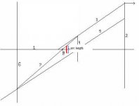
I attached a pic of Guy Grotke's original drawing with my added theory. Basically, instead of putting the lamp at point 8 on the drawing, put it a little forward so the lamps arc ends are just barely intersected at the precondenser's focal "cone"
I might be way off in my thinking...but I thought I'd at least get it out there to see what you all think...
Attachments
makes sense to me
But I think the limiting dimension is actually the width of the arc. (You want to get that width "spread" over the entire height of the LCD.) So the additional distance to move it forward would be much smaller.
In real practice, I think the light intensity of different parts of MH lamp arcs, the effect of the inverse square law on the amount of light striking different parts of the fresnel, etc. all make these "ideal dimensions" much more useful as starting points. Once you fire it up, you can see directly if all the LCD surface is being lit evenly so then you can make adjustments in your distances. Changing the distance between the lamp arc and the pre-condensor lens by just a few mm, can make great differences in the size of the illuminated area at the fresnel.
Decreasing the distance will spread the illuminated cone wider, and vice versa. You may find that a "perfect distance" (so the lit oval just barely covers the LCD corners) gives you uneven lighting. The solution is to decrease the distance just a bit more. You lose some of the light, but get more even results on the screen.
I think the arc lenght is, but the arc placement is not, critical for diy projection, taking into account that most of us don't have access to pro measuring tools and so can't avoid slight placement and alignment errors that will affect the projected image much more... Guy Grotke's patented "paper testing" is far more effective imho than trying to calculate positions in fractions of mm, as you'll have to cope with mm misplacements somewhere or other.
And now my two cents... in GG's original picture the arc of light is beaming slightly misaligned rays, more unuseful the farther their starting point is from the ideal source. In your picture the arc ends are beaming correctly towards their respective fresnel ends, but not to the rest of the fresnel, and the misalignment grows higher in the center of the arc. So if you think that slight misplacement of the arc will help you would be better served spreading the misalignment more evenly, like this:
Btw just returned home after six months, I hope to make some lumen tests with a elliptical 150w and spherical 150w and 400w setups... and build a couple of them damned things at last.
Attachments

- Status
- Not open for further replies.
- Home
- General Interest
- Everything Else
- The Moving Image
- Optics
- Understanding Pre-Condenser lens