Max. current 100mA
Nonsense, it's a yoke. 🙂
This small core will be saturate at even few ten mA current (if this transformer has enough 50-100H- inductance, aka primary turn is about 1500..2500).
15k inductor at 20Hz (required inductance):
15k= 2*pi*f*L
15000=2*pi*20Hz*L
L=15000/(40*pi)
L=119H
If your goal is 40Hz : L=60H
????OPT Edcor tx is no gap core.
Is it a parafeed transformer?
If yes, use tube with CCS as anode load, and connect 1..10uF capacitor between transformer primary and anode (ground transformer another leg).
EDCOR - GXSE5-600-15K spec.
"I am sorry, we do not have the DC resistance on file. The max current (AC+DC) is 100mA. We also do not have the inductance. "
No comment.
"I am sorry, we do not have the DC resistance on file. The max current (AC+DC) is 100mA. We also do not have the inductance. "
No comment.
I don't know, I see the information Edcor forum: EDCOR - Parallel feed transformer for headphone amp project?
????
Is it a parafeed transformer?
If yes, use tube with CCS as anode load, and connect 1..10uF capacitor between transformer primary and anode (ground transformer another leg).
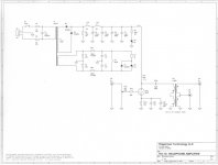
As schematic in post 50 http://www.diyaudio.com/forums/tubes-valves/300896-understanding-load-lines-5.html#post4923487
As schematic in post 50
No, the post 50 schematic is series feed.
This is one of parafeed schematic.
Attachments
In place of 30H choke the CCS, right?
Could I do some DVM measurements to know the primary & secondary DC resistance?
Could I do some DVM measurements to know the primary & secondary DC resistance?
OPT specs taken from Edcor web: http://www.edcorusa.com/gxse5-15k
Wattage 5W
Max. Current 100mA
Primary (input) Impedance 15K Ohms
Screen/Grid Tap 40%
Secondary (output) Impedance Depends on model.
Frequency Response 40~18K Hz., <1dBu
THD+Noise <0.1% @ 1K Hz.
Bobbin Material Nylon 6/6 GF-30
Flamability Rating Class B 130°C
Core Material M-6 29 ga. grain oriented lamination steel
Secondary Insulation (transformer) Clear air dry polyester varnish
Termination 0.187" (3/16") quick disconnects
Mounting Zinc plated steel channel/frame
Weight 1.2 lbs.
Compliance RoHS & REACH
Last edited:
Could I left the CCS to 20mA , the grid -3V and plate voltage 88V or I have to change something to improve the sound quality.
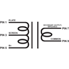
Edcor pin 1 to output cap, pins 5 & 9 to ground and pin 7 output, right?
Right.
Could I left the CCS to 20mA , the grid -3V and plate voltage 88V or I have to change something to improve the sound quality.
Tomorrow I will add the OPT, now I'm tired. Thanks for all help I will keep us informed.
Could I left the CCS to 20mA , the grid -3V and plate voltage 88V
You can only have two independent variables. With the current set to 20mA and the grid at -3V the plate voltage will settle were it needs to. As the tube ages the plate voltage will increase over time.
For example I want to understand the load line for 5687 tube, I have 209V as B+ and 10K as load anode resistor.
To know the plate current is to divide 209V : 10.000 ohms = 0.0209 A = 20,9mA.
Now I draw a line between these points to get the load line, If I choose the operating point at -3V as grid voltage the tube will draw 12mA, right? If I want each tube draws 10mA the grid voltage have to be -4.5V? The best OP is -7V as grid voltage?
How to know the best plate current for each tube?
Hi Merlin,
You might also find Paul Joppa's article on Operating points helpful. They are from Bottlehead's magazine archive of Valve: 1998 Vols. 3,4,& 5.
I agree. Many posts and still not putting 3 parts together so they will work.
There is a vast body of information on Basic DC, AC theory, and then (only when you have mastered DC and some AC) Amplifiers. This must exist in Spanish(?), but it is clear you are fluent enough in English to read and digest electric and electronic theory in English.
Asking us to type-up very basic explanations of very basic design hurts our fingers and my back/leg.
Hi Merlin,
You might also find Paul Joppa's article on Operating points helpful. They are from Bottlehead's magazine archive of Valve: 1998 Vols. 3,4,& 5.
Thanks for the link.
You can only have two independent variables. With the current set to 20mA and the grid at -3V the plate voltage will settle were it needs to. As the tube ages the plate voltage will increase over time.
That's a very good information, many thanks John.
Happy Xmas for everybody.
The point is, how precise is DS or SIM.Simulator says 14.2mA in place of 12mA?
- Status
- Not open for further replies.
- Home
- Amplifiers
- Tubes / Valves
- Understanding load lines