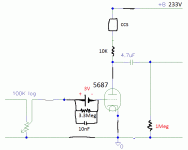
Oh my good, you are right I don't need the anode resistor, I only need to set the CCS to 25mA.
Thanks Groucho2004
Thanks Groucho2004
Last edited:
Merlin, a CCS maintains a constant current. So if it resists changes in current despite the tube trying to modulate current with the input signal, that means it has a very high impedance. In other words, the CCS is very good at converting current changes to voltage changes (the basic principal of amplifying with a grounded cathode triode). Many times we assume the impedance of a CCS to be infinite (for simplicity). What is infinity plus 10k? 🙂
You could use the resistor to drop voltage so that it is lower at the anode of the tube (maybe that is why you include it), but the resistor is not needed as a load.
edit: You figured it out before I was done typing 🙂
You could use the resistor to drop voltage so that it is lower at the anode of the tube (maybe that is why you include it), but the resistor is not needed as a load.
edit: You figured it out before I was done typing 🙂
What's happen if I have B+ 114,5V and CCS 15.7mA each tube and grid voltage -3V. I ask because if I draw a load line the grid voltage have to be near -4V at the grid and I have -3V?
Attachments
Last edited:
If I want that tube works at 10mA setting my CCS to 20mA (10mA for each tube) with -3V grid have I to reduce B+ to 80V?
Last edited:
You want to parallel the two systems of the valve?If I want that tube works at 10mA setting my CCS to 20mA (10mA for each tube)
If I want that tube works at 10mA setting my CCS to 20mA (10mA for each tube) with -3V grid have I to reduce B+ to 80V?
What's happen if I have B+ 114,5V and CCS 15.7mA each tube and grid voltage -3V. I ask because if I draw a load line the grid voltage have to be near -4V at the grid and I have -3V?
Oscillate?
Any answer?
TIA
Felipe
Felipe, I don't understand you goal.
Gain of CCS loaded 5687 is about 25dB, horrible for preamp.
The Maida"s CCS is good for PSU, but a crap compare to correct anode load CCSs (for example commonly used DN2540 cascode CCS).
Paralleling 5687 halves is pointless. Better Rout, but you have increased distortion (due to the not identical halves).
What is your goal?
Driving 100k input impedance is very easy task, any source can do it.
Felipe, I don't understand you goal.
Gain of CCS loaded 5687 is about 25dB, horrible for preamp.
Why: because is a lot of gain?
The Maida"s CCS is good for PSU, but a crap compare to correct anode load CCSs (for example commonly used DN2540 cascode CCS).
Yes I know but at this moment don't have any DN2540
Paralleling 5687 halves is pointless. Better Rout, but you have increased distortion (due to the not identical halves).
I don't want to parallel tubes
What is your goal?
Driving 100k input impedance is very easy task, any source can do it.
Yes I know
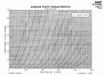
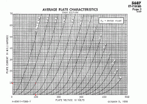
The 5687 tube preamp is to learn how get the best sound using the load lines but to do so I have to know how to use it and understand what's happen if for example I don't follow the load lines?
Why If I have at real circuit CCS 20mA, B+ 100V at the anode and -3.192V at grid, load lines says that I have near -4V at grid?
Attachments
Last edited:
> B+ 100V at the anode
"B+" is the (plate) Battery voltage. Here, 233V
The plate always sits somewhat lower.
Bias conditions will set plate voltage.
> load lines says that I have near -4V at grid?
I do not see any load-line on that image.
Your hard-spec seems to be the 3V battery bias, because batteries do not come in arbitrary voltages.
Your wish-spec is the 10mA per tube current. This will be *forced* by a 10mA CSS.
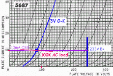
The intersection of 3V g-k and 10mA seems to be 85V. This *will* be your plate voltage (assuming your specific tube matches the published curve.... it will be close but never spot-on.)
You seem to get 48V plate swing for 3V grid swing. Gain is near 16. Theory suggests a CC-loaded triode will have voltage gain near Mu. As Mu for this tube near this current is 16, we are not surprised.
The 100K AC load shifts AC swing to the red line. Not very different at all. Squinting, we suspect 47V out, gain like 15.7. Actually if you run two tubes, this should be 200K per tube, but I'm not going to squint that small.
Tangent to plate line for Vgk=3V is about 2,750 Ohms. Since the CCS is infinite, and 100K-200K is very-very-large, we may pencil output impedance as 2,713 Ohms for one tube or 1,360 for two tubes.
I "know" a 1K source can drive 10,000pFd to past 15KHz. If you run a 10 meter cable that is near 300pFd, 33 times better, 500KHz, which is way-ample for audio.
A rule-o-thumb for resistance loaded triode is 5% THD at maximum swing. Here you swing half of maximum voltage, say 2.5%. CSS improves that. And since you probably need only 2V of the available 47V swing, THD may be well below 0.2%, and maybe near 0.1%, at Maximum output. If your power amp is similar old-style it will be running 3%-5% THD at this level. The line-amp distortion is insignificant.
The combined 20mA CSS will dissipate 3 Watts normally and 4W when the battery goes flat. It will need a heatsink.
Attachments
Last edited:
>The intersection of 3V g-k and 10mA seems to be 85V. This *will* be your plate voltage (assuming your specific tube matches the published curve.... it will be close but never spot-on.)
The 15V of difference is normal? Is +16% more than expected?
My battery have 3V and is connected the minus side to the grid please see post 21 http://www.diyaudio.com/forums/tubes-valves/300896-understanding-load-lines-3.html#post4922395
The 15V of difference is normal? Is +16% more than expected?
After adjust well the CCS now I have 88V at the plate🙂
- Status
- Not open for further replies.
- Home
- Amplifiers
- Tubes / Valves
- Understanding load lines


