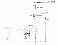
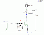
I want to try the 5687 as headphone amp for my Sennheisser HD600 300 ohms, to the pourpose I have OPT Edcor 15K / 600 ohms.
I want to use the same B+ 88V at plate that I have now the CCS set to 20mA (I have to change to 22mA for OPT), to draw the load line for Transformer/Choke Loaded I attached the load line, I'm open for other OP and CCS but I want to stay at -3V at grid if possible all to improve the SQ.
Attached is the pic with the load line waiting your comments.
TIA
Felipe
Attachments
Last edited:
The schematic above will produce (almost) no ac signal at the OPTs primary and secondary winding. Trying to figure out why would be a good exercise for you.
Again - get some books, there have to be some in Spanish.
Again - get some books, there have to be some in Spanish.
Last edited:
This is getting ridiculous. The CCS has a near infinite impedance and therefore the current through the OPT does not change, be it dc or ac. The explanation for this is in this very thread and even though you keep saying that you understand, you clearly don't.
Either learn electronics or stick to proven schematics/kits. Otherwise you will keep posting thousands of questions and not understand the answers.
Either learn electronics or stick to proven schematics/kits. Otherwise you will keep posting thousands of questions and not understand the answers.
A good and kind friend told me that I need to isolate the CCS, if I do not isolate the CCS will be part of the amp.
Attachments
Last edited:
That doesn't write and speak and understand English very well doesn't mean I can understand this answer from my friend.
Use a CCS fed shunt regulator to supply B+ to the transformer (check out the Salas HV shunt reg. thread). Set the reg. output to 90V and with your fixed battery bias the plate current should fall in line. With a single-ended application the shunt current will need to equal the bias current of the tube. Total current supplied by the CCS will be twice the bias current and size heat sink for the shunt device for that current across the 90V for safety in case tube fails.
I should probably add that the transformer load is not the same as a CCS load and the load lines will be very different. What may be optimum for a CCS load may well not be for a transformer load. You need to draw it out on the plate curves and check. It could be that you will want a different OP. Your battery "fixes" the grid bias. If the shunt reg. is adjustable you could change the B+ voltage and see how that changes the bias current and shifts the load line.
1.) CCS totally unnecessary if you use OPT.
2.) 5687 Ri is about 2k at 23mA, so required OPT is 8k:150..300..600 (if you have high impedance headphone). If you have low impedance headphone, use small 8k:8..16 OPT.
3.) If you have 25mA capable 15k:600 transformer, you are a lucky (and rich 🙂 ) man. This (good) transformer are horrible pricey, 200..600 Eur/pair!
1.) CCS totally unnecessary if you use OPT.
2.) 5687 Ri is about 2k at 23mA, so required OPT is 8k:150..300..600 (if you have high impedance headphone). If you have low impedance headphone, use small 8k:8..16 OPT.
3.) If you have 25mA capable 15k:600 transformer, you are a lucky (and rich 🙂 ) man. This (good) transformer are horrible pricey, 200..600 Eur/pair!
What B+ for only the 15K:600 transformer with grid bias -3VDC?
What B+ for only the 15K:600 transformer with grid bias -3VDC?
Choose an OP and draw a load line. The B+ will be the plate voltage at the OP plus the voltage loss in the output transformer (winding resistance x bias current).
- Status
- Not open for further replies.
- Home
- Amplifiers
- Tubes / Valves
- Understanding load lines
![WP_20161220_002[1].jpg](/community/data/attachments/541/541035-95cae58d204077a205f88c26df2c4892.jpg?hash=lcrljSBAd6)


![WP_20161220_004[1].jpg](/community/data/attachments/541/541176-9cad62c9acd4bf80928c64624d110a1e.jpg?hash=nK1iyazUv4)
![WP_20161220_006[1].jpg](/community/data/attachments/541/541324-b14f45fa7d886998367a8b8b08a544e4.jpg?hash=sU9F-n2IaZ)