And here's a simplified, DC-coupled version with a +410V B supply (just an experiment, hasn't been built).
--
edit to add:
I think I'd have to re-think the decoupling. Maybe re-jigger things so the plate load on the first stage is 33k ohms and leave out the 2k2 and 47uF decoupling network. Use a Maida-style regulated B+ (410V). Or just build the ImPasse as is.
My goal is to drive a power amp that has a 5687 LTP as push-pull driver for PP 2A3's. Balanced inputs. It will take about 5V pk (10V pk-pk) signal to drive it to clipping. I guess I'd like about 1V pk input to line amp to power amp clipping. That would require 5X gain from the line stage.
--
--
edit to add:
I think I'd have to re-think the decoupling. Maybe re-jigger things so the plate load on the first stage is 33k ohms and leave out the 2k2 and 47uF decoupling network. Use a Maida-style regulated B+ (410V). Or just build the ImPasse as is.
My goal is to drive a power amp that has a 5687 LTP as push-pull driver for PP 2A3's. Balanced inputs. It will take about 5V pk (10V pk-pk) signal to drive it to clipping. I guess I'd like about 1V pk input to line amp to power amp clipping. That would require 5X gain from the line stage.
--
Attachments
Last edited:
Sorry I had got it into my head that the rp of a 5687 was lower. The Jenson looks like a good candidate, though with that sort of step down you can probably get more than adequate results from one of the EDCOR offerings at a fraction of the price. Also aren't the Cinimags very affordable in America.
I would place the transformer at the output simply to make the preamplifier universally applicable rather than specific to the particular poweramp. The current driving capability of the preamp output transformer will overcome any issues associated with cable parasitics. I think the principle of 600Ohm drive in professional setups is that 600R drive will crush all nasties and deliver the cleanest signal to the load. High impedance output transformers are much more prone to self resonance and generally need loading down or zobels to get a clean response out past 50khz or so, otherwise they tend to have a rising response which is very noticeable.
Shoog
Last edited:
Thanks again for more info!
I have a friend who wants to hear a tube preamp feeding his powered speakers (QSC K8), to hear for himself what all this fuss over tubes is about. That's why I was thinking of a preamp with balanced outputs in the first place. Then I got the idea (from various sources) that an input transformer on the power amp would be cheaper and better performing. So I started looking at things like the Jensen JT11P-1. Edcor has a 0.5W 10K:10K transformer that should work, as well as 15K:10K and 15K:15K versions, but none have shielding cans. They certainly are inexpensive (less than $15 USD each). I should probably just buy a pair and see how that works.
Now, if I'm following correctly what you've been saying, I could feed a 4:1 transformer in parafeed mode from a cathode follower or maybe a common cathode 6e5P-triode, and get good performance that way. If the primary is specified at 2k4 impedance, and it's a 4:1 transformer, then the secondary will have a very low impedance (150R?). Will the primary inductance be high enough to get decent bass response from the preamp?
Looking at this Edcor 2:1 line matching transformer -- https://www.edcorusa.com/wsm600-150 -- I see that the primary impedance is only 3H.
Driven from a 200R output impedance (like a 5687 cathode follower), that would put the f3 at about 10Hz. That's not all that great, but is probably acceptable.
Edcor's 10K:600 XSM (2 watt) transformer -- https://www.edcorusa.com/xsm10k-600 -- shows 40H for the primary inductance. That's a little better.
It looks like there are compromises to be made everywhere I turn. There's a lesson in there... Everything is a compromise.
It sure is easier to deal with only R's and C's.
--

Correct,
but if you will use it on input you have also a double choice, unbal and, in case, balanced .
Then you can use a SRPP with 6922 (each row) with a reasonable gain and low output impedance.
If you need less gain you can use a 6H6 tube, it is cheap and good fot his purpose.
Walter
but if you will use it on input you have also a double choice, unbal and, in case, balanced .
Then you can use a SRPP with 6922 (each row) with a reasonable gain and low output impedance.
If you need less gain you can use a 6H6 tube, it is cheap and good fot his purpose.
Walter
If you are going to do parafeed this is the way to do it. It removes the need for a cathode bypass cap since the AC potential of the tube cathode is virtual ground. It also reduces the sonic impact of the parafeed cap since the cap altered signal is used to modify the degenerative feedback of the valve.
Shoog
Shoog
Attachments
waltube:
That is the dilemma. Xfmr on the output of the preamp, or on the input of the power amp. On the output of the preamp, the xfmr can have a 4:1 ratio, which might make it easier to get a cheap one that performs well. $13 USD for an Edcor 10K:600 looks pretty good. The problem with the input transformer is that it will need to be high impedance on both primary and secondary windings, increasing complexity. On top of that, it will definitely need to be in a mu-metal can to shield it from the various other xfmrs on the power amp. That means the input xfmr will cost a lot of money. The Jensen JT11P-1 is about $70 each. Lundahl LL1540 is a bit more. I could get an Edcor 15K:15K, but it would be bare, no shielding can. I'm worried about hum induced from the plate chokes I'm using on my 6N6P push-pull driver stage.
Shoog:
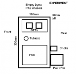
I'm still worried about how to keep induced hum from the power xfmr (and maybe power supply choke) out of a bare output xfmr. I have a gutted Dyna PAS chassis (steel) to work with. The power transformer will be mounted on the back panel of the chassis, hanging outside. I figure the OPT's will be inside the chassis, mounted on a non-conductive plate (masonite?). I will use some kind of non-conductive plate to mount the power xfmr. Maybe something like Garolite, or whatever that stuff is called.
The only reason using transformers is more complicated than just adding a split-load inverter is layout and worries about induced hum.
--
I forgot to mention -- The volume control is a Slagle tapped autoformer, and the selector switch is a Niles Audio thing I picked up years ago. Each is in its own box, connected by short interconnects (unbalanced, RCA). If this experiment works out, I plan to incorporate all these pieces into a single, nice chassis. This is still an experiment. I've been using a 6N6P common cathode as my line stage for a long time now, unbalanced into the PP 2A3. It's time to take advantage of the power amp's balanced inputs.
--
That is the dilemma. Xfmr on the output of the preamp, or on the input of the power amp. On the output of the preamp, the xfmr can have a 4:1 ratio, which might make it easier to get a cheap one that performs well. $13 USD for an Edcor 10K:600 looks pretty good. The problem with the input transformer is that it will need to be high impedance on both primary and secondary windings, increasing complexity. On top of that, it will definitely need to be in a mu-metal can to shield it from the various other xfmrs on the power amp. That means the input xfmr will cost a lot of money. The Jensen JT11P-1 is about $70 each. Lundahl LL1540 is a bit more. I could get an Edcor 15K:15K, but it would be bare, no shielding can. I'm worried about hum induced from the plate chokes I'm using on my 6N6P push-pull driver stage.
Shoog:
I'm still worried about how to keep induced hum from the power xfmr (and maybe power supply choke) out of a bare output xfmr. I have a gutted Dyna PAS chassis (steel) to work with. The power transformer will be mounted on the back panel of the chassis, hanging outside. I figure the OPT's will be inside the chassis, mounted on a non-conductive plate (masonite?). I will use some kind of non-conductive plate to mount the power xfmr. Maybe something like Garolite, or whatever that stuff is called.
The only reason using transformers is more complicated than just adding a split-load inverter is layout and worries about induced hum.
--
I forgot to mention -- The volume control is a Slagle tapped autoformer, and the selector switch is a Niles Audio thing I picked up years ago. Each is in its own box, connected by short interconnects (unbalanced, RCA). If this experiment works out, I plan to incorporate all these pieces into a single, nice chassis. This is still an experiment. I've been using a 6N6P common cathode as my line stage for a long time now, unbalanced into the PP 2A3. It's time to take advantage of the power amp's balanced inputs.
--
Attachments
Last edited:
I haven't had issues with induced hum and some of my input/output transformers have been screened and some haven't. Sensible placement is essential and then if you can incorporate it an aluminium box with a ground wire should make an adequate screening can. Think 1/4" thickness aluminium. The only times I did get problems with induced hum is when the power transformer saturates and then starts spewing huge amounts of field into the case. I had this with my last vlave build on a underspec'd negative supply, I replaced it and the problem was gone.
Having the power/chokes on one face of the case and the signal transformers on the other should also help a lot.
My speakers make just 1mV of hum audible so I wouldn't sweat it to much.
Shoog
Having the power/chokes on one face of the case and the signal transformers on the other should also help a lot.
My speakers make just 1mV of hum audible so I wouldn't sweat it to much.
Shoog
Thanks Shoog. That's encouraging. 1/4" thickness aluminum box.... Maybe one of those die-cast aluminum boxes used for guitar stompboxes, but with a flanged base, so that I can bolt it to the chassis. Hammond Mfg. - 1590 "F" Series - Diecast Aluminum - Flanged Photo Tables

You know that makes this even more expensive, don'cha? 🙂
--
You know that makes this even more expensive, don'cha? 🙂
--
You need continuous (or almost continuous) electrical contact along the joints/seems to get effective screening from UHF interference.
Its inductive coupling which is Rongon's main concern and thats why aluminium was suggested over mu-metal or something more appropriate for radio interference. Iron would also do, but I think silicon Iron is best.
i was researching this myself since my latest solid state build has a small induced hum from the power toroid and the Studio crowd were suggesting aluminum shielding as a way of damping it.
I would build without and only add it if it proves essential.
Shoog
i was researching this myself since my latest solid state build has a small induced hum from the power toroid and the Studio crowd were suggesting aluminum shielding as a way of damping it.
I would build without and only add it if it proves essential.
Shoog
Last edited:
I never use a cheaper trafos for audio purpose.
I use the 3575 also in OCC wire for coupling the dac with output stage, but also for input on power amp to have the phase splitter from the beginning.
The bandwidth is very large and the max input level is very high also at low frequency.
I prefer the use in input because you don't have the bad thing to decrease the ouput voltage ( as for output use) that means a lower ratio s/n.
Walter
I never use a cheaper trafos for audio purpose.
I wouldn't either, if I could afford to blow $150 or more on an experiment. But funds are limited.
I'm still not convinced the use of the transformer is worth the extra money compared to wiring up a cathodyne (split-load inverter) with enough standing current to make a decent output stage. I don't think it's a valid argument that you can't use a cathodyne single-ended. If you accept that you have to use the inverted output (the cathode feed from the cathodyne), you can use that as the one output and ground the plate feed after its coupling cap. (This was explained in SY's ImPasse article, and it makes sense to me.)
I think I'm going to build a version with a cathodyne as the output stage, and figure out a transformer coupled version for a comparison.
The next question is whether that transformer should be an output transformer on the line stage or an input transformer on the power amp (used as the phase splitter). I'll need a 'preamp with gain' in either case.
1) The loss of gain from using a 2:1 or 4:1 OPT doesn't bother me, unless the S/N ratio really suffers. I don't need much gain, only about 6X before the power amp inputs. There are several good triodes and triode-wired pentodes that can yield 25X gain (or more) with low distortion and low output Z. I can afford to step down to 6X voltage gain.
2) I have read from people whose judgment I trust that all things being equal, a 1:1 transformer is going to perform best. That's why I was looking at the Edcor equivalents of the Jensen JT11-P and similar (the Sowter 3575 is pretty similar to that).
3) I have also read from people whose judgment I trust that a 4:1 OPT can work great in parafeed arrangement on the output of a preamp. I believe Lynn Olson was one of them.
Since incorporating transformer coupling is going to be expensive, and will take some extra work to get right, and not forgetting that I do not have unlimited funds for this, I'm caught on the horns of a dilemma.
Since I need to do this on the cheap, and all things being equal between two transformers, is it more likely that I'll get better bandwidth, lower leakage inductance, and lower interwinding capacitance from a 4:1 OPT with a low Z secondary, or a 1:1 input xfmr with high Z primary and secondary?
I ask this because Edcor's offerings are all wound on similar cores. Their XSM transformers all have the same core, while their WSM transformers all have a different (smaller) core. Both XSM and WSM can be ordered with 10K:600 or 15K:15K windings.
In the meantime, I think the Dyna PAS chassis is destined to become something like an ImPasse, with the cathodyne phase splitter as the output stage.
I have a stripped and cleaned Heath W5 chassis I can use for a stereo preamp with OPT's. That chassis will be better because it has more room to get the OPT's away from the power supply iron.
--
Last edited:
You are going to be happier with a cheap step down than a cheap 1:1, thats your answer. Bandwidth is going to be better and your inductance is going to support lower notes.
I personally would use both an output transformer on the preamp and an input transformer on the power amp - but if I had to choose it would be the output which would offer most flexibility and performance. The way I have it setup it allows me to have two output of different phase which is very useful when presented with biamping and multiple amps.
Go with the XSM for cleaner deeper bass.
Shoog
You maybe interested in this quote from another thread;
Just saw you responded to this. Wait and see how it sounds in your setup, as you said its difficult to see where the problem in the midrange is coming from. I would also consider trying the mu-follower as a good compromise parafeed arrangement.
Shoog
Edcors are no good for line out transformers. I tried one of there 10k to 600 ohm matching transformer parafeed connected. It did not sound good at all. It sounded like the midrange was missing in the sound. This really sucked because I'm cheap and those edcors are the right price at around 15 bucks or so. Next time I'll use either cinemag or magnequest.. The cinemags are the cheapest.
Nick
Just saw you responded to this. Wait and see how it sounds in your setup, as you said its difficult to see where the problem in the midrange is coming from. I would also consider trying the mu-follower as a good compromise parafeed arrangement.
Shoog
Last edited:
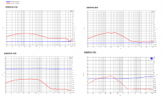
Thanks again. Last night, before I saw your last post, I bought a pair of XSM10k:600, along with a pair of WSM15k:15k (what the heck, maybe I'll learn something).
I picked those two because their frequency response graphs showed the least rise in high frequencies.
The XSM10k:10k doesn't look so good (rising treble response). WSM15k-15k response looks smoother. Also, not all of Edcor's offerings have frequency response charts available, so I had to make a decision based on limited data.
Of course, I don't know how valid those charts are, or how well they represent real-life performance.
It'll be 6 weeks or so before the transformers arrive.
--
Attachments
I went searching for some other opinions and found that the professional studio people generally love the EDCORS. I think its all down to implementation. I would be looking at pushing at least 10-15mA of standing current at them using a mu-follower to preserve gain but lower output impedance. With step down its not difficult to get flat response out to 50Khz if you drive them sensibly. Thats why I would go for something like the 5697 which is more capable of higher bias currents than most medium mu valves.
The other good option for a driver is the SLCF which has two stages meaning you can choose whatever gain you like in the input - and then a very linear cathode follower to push the output. I have two and they work extremely well.
Shoog
The other good option for a driver is the SLCF which has two stages meaning you can choose whatever gain you like in the input - and then a very linear cathode follower to push the output. I have two and they work extremely well.
Shoog
I would be looking at pushing at least 10-15mA of standing current at them using a mu-follower to preserve gain but lower output impedance.
Why so much current? (I don't understand, and I'm curious...)
I have a lot of 5687, so that would work for me.
I will need about 5Vpk maximum output from the preamp. Since the xfmr will have a 4:1 stepdown, that means 20Vpk on the primary, correct?
If yes, then I might need more gain than a 5687 can provide. Maybe a 6DJ8 mu-follower. That can be done with 10mA plate current, maybe 12mA.
The Super Linear Cathode Follower is new to me. I'll have to look into that.
--
- Status
- Not open for further replies.
- Home
- Amplifiers
- Tubes / Valves
- Unbalanced In > Balanced Out line amp - How To Do It?