Here is a simple web tool if all you need to know is the turns required for a specified inductance....
Toroid Winding Calculator ? 66pacific.com
do you have a link for ee cores inductor calculator
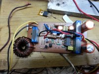
Well, I think I really screwed up my amp. I finally finished building the simple class D amp, from etching to populating with all the parts, winding my own inductor, (T106-2). All I had was a simple + and - power supply with two 6800uF caps, one on each rail, and a VH248 bridge rectifier, which is a 6 amp, 200 volt rectifier. My transformer was a 17-0-17 toroid transformer, so I figured aprox. +- 23vdc. So, I hooked it up, turned it on, and the bridge rectifier blew within seconds. I turned it off right away. It didn't look like anything happened to the amp, no smoke or heat or anything. I tested the power supply beforehand and it worked fine. I guess I need to build a really decent power supply and not mess around with quicky built supplies. So, what did I possible screw up on the amp? You can yell at me if you want.
Attachments
Well, I think I really screwed up my amp. I finally finished building the simple class D amp, from etching to populating with all the parts, winding my own inductor, (T106-2). All I had was a simple + and - power supply with two 6800uF caps, one on each rail, and a VH248 bridge rectifier, which is a 6 amp, 200 volt rectifier. My transformer was a 17-0-17 toroid transformer, so I figured aprox. +- 23vdc. So, I hooked it up, turned it on, and the bridge rectifier blew within seconds. I turned it off right away. It didn't look like anything happened to the amp, no smoke or heat or anything. I tested the power supply beforehand and it worked fine. I guess I need to build a really decent power supply and not mess around with quicky built supplies. So, what did I possible screw up on the amp? You can yell at me if you want.
hi please use a 100wt bulb in series with ac to power supply when powering any first project 🙂
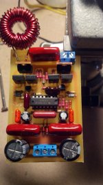
Here's my compact layout based on original schem by ejtagle.
Is it tested ????? 😕
D
Deleted member 148505
Is it tested ????? 😕
ERC and DRC tested in EAGLE. As long as the schematic is correct, the board will surely work.
You have to do manual electrical testing if you etch your own board.
ERC and DRC tested in EAGLE. As long as the schematic is correct, the board will surely work.
You have to do manual electrical testing if you etch your own board.
then im starting tommorow,can this run at +- 20v?
I have Stewin's boards and this is the noise coming out of the speakers with the input grounded. What could be the problem?
Regards.
It could be a bad opamp,grounding connection,source,or most probably emi
hi all
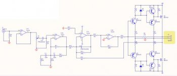
i am doing a ucd version of this amp all credit goes to etjagle the designer. i am combining lory laci input stage, as it has less noise and lorylaci has taken measures of his amp and wave forms are o.k . my board will be big and i am doing single sided.
i am doing a ucd version of this amp all credit goes to etjagle the designer. i am combining lory laci input stage, as it has less noise and lorylaci has taken measures of his amp and wave forms are o.k . my board will be big and i am doing single sided.
Attachments
-
Class D 200 Wrms with 2 mosfet single sided ucd style schematic.pdf23.6 KB · Views: 413
-
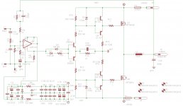 Class D 200 Wrms with 2 mosfet ucd style schematic.jpg156.4 KB · Views: 1,313
 -
Class D 200 Wrms with 2 mosfet single sided ucd style board.pdf56 KB · Views: 412
-
 Class D 200 Wrms with 2 mosfet ucd style board.jpg144.7 KB · Views: 1,292
the pcb files of the project
Attachments
Thanks to Norazmi.
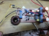
So I finally built this simple Class D amp,my first.
It had a moderate sized heat sink which got mild warm after an hour of working.
It worked fine with 8ohm loudspeaker .but when driven to a 4 ohm woofer,IRF9640 failed within seconds.
What could be the reasons?
So I finally built this simple Class D amp,my first.
It had a moderate sized heat sink which got mild warm after an hour of working.
It worked fine with 8ohm loudspeaker .but when driven to a 4 ohm woofer,IRF9640 failed within seconds.
What could be the reasons?
Attachments
Last edited:
i had the same problem and i was very confused because my earlier versions of this amp worked perfectly . but when i used irf 9640 it failed even three hours after working properly. when i changed to irf540n and irf9540n everything is o.k up to now even when using 4ohms at +/-50vlts
Thanks stewin ,I shall try IRF9540s.i had the same problem and i was very confused because my earlier versions of this amp worked perfectly . but when i used irf 9640 it failed even three hours after working properly. when i changed to irf540n and irf9540n everything is o.k up to now even when using 4ohms at +/-50vlts
So it means IRF9640 is not suitable for this application.
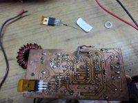
What could be the reasons? I guess the amp oscillated beyond its operating frequency as there was sudden rise in temperature in Inductor.
My power supply was 34-0-34 dc ,(150va ) with 4700uf capacitors.
D
Deleted member 148505
You are using micrometals material no. 2, it should run cooler with increasing osc. frequency. I think it's hot because of high shoot through current.
IRF9640 has lower Qg which means it has higher switching speed, you should increase the deadtime by adding gate resistors.
IRF9640 has lower Qg which means it has higher switching speed, you should increase the deadtime by adding gate resistors.
Thanks Jlester,You are using micrometals material no. 2, it should run cooler with increasing osc. frequency. I think it's hot because of high shoot through current.
IRF9640 has lower Qg which means it has higher switching speed, you should increase the deadtime by adding gate resistors.
Or, I am thinking whether I should drop this circuit and build one with IR2110.
- Home
- Amplifiers
- Class D
- Ultra Simple Class D