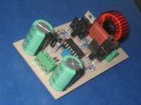
specified ur inductor specs, such as core material, uh, coil size... because of large current draw through inductor, improper coil size or winding may cause it vibrating.
i am using EI33 from old Computer PSU, 33 turn of AWG20 coil size
And thats the gap size ?i am using EI33 from old Computer PSU, 33 turn of AWG20 coil size
And thats the gap size ?
no gap, i don't know how to make a gap. it very dificult to cut
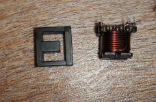
cut it with mini drill, using circular saw for smooth metal. Thats why ur coil filter getting hot. Ferrite core with no gaps will cause heat up fast or may burn .
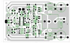
No need to cut , just place a bits of carton or plastic (1,5-2mm thick) between the side legs of the EI33.no gap, i don't know how to make a gap. it very dificult to cut
Follow the red arrows😀
Attachments

thanks dimonis GOD bless you man .
can you do the same with etd series cores 2.5mm each side of E core?
can you do the same with etd series cores 2.5mm each side of E core?
Last edited:
No need to cut , just place a bits of carton or plastic (1,5-2mm thick) between the side legs of the EI33.
Follow the red arrows😀
and how many turn i need for 8ohm/150watt rms subwoofer?
what is better, AWG20 or 5 x 0.3mm litz wire?
Glo
Hi Norazmi, problem solved. I found some EE core with 1 mm gap from old charger. I add the gap to 3mm, then make 55 turn of AWG20. No ringing even with max volume, and stay cold.
regards
glo
regards
glo
hi norazmi, any change to supply this amp with +/- 60VDC ? i want to obtain 200 watt rms in 8ohm
regards,
glo
regards,
glo
not more than +/- 50 vdc 😀 . I do not test with more than +/-50, few modification is needed and i`m not suggest u to go with more than +/- 50 with N and P channel mosfet. You should use another circuit with N only mosfet to go with hi power version, such as using IR2110 or fully discrete ucd amp.
Great!
The biggest bang for the buck! 😛
I think I could try to do it myself... I have tons of TL084 somewhere...
I've now discovered that TL084 is an "high-speed operational amplifiers", as described in datasheet. My world is starting to change.
The biggest bang for the buck! 😛
I think I could try to do it myself... I have tons of TL084 somewhere...
I've now discovered that TL084 is an "high-speed operational amplifiers", as described in datasheet. My world is starting to change.
... my pcb is just like schematic! whats the problem?
This is a big problem! PCB is not schematic. On a schematic a wire can be as long as you want, but on PCB wire has inductance. To be more specific: supply decoupler capacitors has to be as close to MOSFETs as possible.
BTW:
I don't see the schematic, because the attached one seems to be invalid on my computer. Picture would be better than zip.
norazmi,
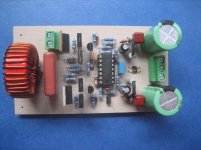
Upon testing my build at 8 ohms impedance, I find out that those 220ohm collector resistors tied to ground was overheating. I'm using 22uh at T106-2 red core inductor and I'm only using +/-18vac for a test. BDs and the inductor coil are getting warm to touch. It does sound pretty good though...
One more thing, in the original schematic it was indicated 47uh for 4ohm and 100uh for 8 ohms. Do I need to add more turns on the inductor?
Regards!
- Home
- Amplifiers
- Class D
- Ultra Simple Class D