hi,
Irvy nice setup. 8mv dc very good.
CPX : add inductor at the output, as schema says at the bottom inductor its a must. 2 TL072 = 1 TL074 and use TL074. i just simulate it with LTspice and it works good. there is no noise at all. i already done tested IRF540N and IRF9540 with 4 ohm load +/- 45 vdc mosfet only warming up. Power supply need enough current to provide full power. at least 5amp with 8 ohm and 8 amp with 4 ohm.
regards.
Azmi.
Thanks norazmi for answering me.
At first look i thought it is a class Ab amplifier since i do not understand the text under "Notas" except Sorenson Audio experiment .I looked that up and i am trying to exactly understand how it works.
In my opinion using tl072 as comparator is a very bad ideea since it is extremely slow(>20us propagation delay).Please post THD, IMD at minimum 4 amps,also switching residual .. i am very curios...
Last edited:
It is apparently self-oscillating, hence self-adjusted with negative feedback loop. Being such a design a little delay error is ironed by feedback. Switching frequency is lowered with audio signal deviation from 0V, being the lowest near clipping.
A somewhat faster comparator could make regions near clipping somewhat nicer, but not by much.
I'd say this is a good design 🙂
A somewhat faster comparator could make regions near clipping somewhat nicer, but not by much.
I'd say this is a good design 🙂
Looks like a nice little amp, but is this really class D?!!? Looks like a MOSFET output class AB design from here. Regardless, building a working amp of any class this way is no mean feat. Congratulations on success, regardless. There are 800 page books out there regarding how to get a class AB amp working properly, and to do it successfully on the first try is really great!

With self-oscillating PWM it is not supposed to be steady. It works better this way.
My guess - for some reason MOSFETs are not switching properly e.g. there is less than 10V peak at MOSFET gates. What kind of zenners did you use?
My guess - for some reason MOSFETs are not switching properly e.g. there is less than 10V peak at MOSFET gates. What kind of zenners did you use?
here is my component value.my supply voltage is +/-43v DC.
the zeners are 5.1v for tl074 supply and 12v parallel with 1k resistor.
i use similar MJE340-350 instead of BD139-140 but there is no difference.
also i change irfp630-9530 with irfp540-9540 but nothing change.🙁
However my simulation on proteus works right and initial PWM is stable and change right by input signal.🙄
Attachments
LOL, rezamir ur output filter cap is 1nf? correct it with 1UF @ 680nf. i`ll check others component not finish yet.
This is original schema, credit goes to the owner ejtagle from forosdeelectronica, as u wish u can always make your own design for the pcb, in class D make it as compact as possible, note that this module stable within maximum voltage is +/- 50vdc and do not go more than that voltage unless u`re experience in class D for component adjustment. bd139 and bd140 will provide heat, if more than its maximum voltage it might be burn. so please follow the maximum voltage with the component listed on schematic.
p/s - see attachment. original compress as .rar and i rename it to .zip, you can rename it back to .rar
best regards,
Azmi
Hello
How do you provide a dead time in your schematic for the mosfet, so they would not switch on at same time ?
And where do you adjust that dead time in your schematic ?
Thank you
Bye
Gaetan
Last edited:
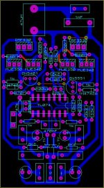
Rezamir nice board. 😀
please measure output offset, voltage at gate for each mosfet, many have build this amp, so far no problem about mosfet heating fast as long as u not reach +/- 50. Did u try with BD139 and BD140? i`m suspect there something error with ur component please double check it at your board. i`ve check 50% of your board seems to be ok.
btw what is the red trace for? on your board have blue trace and red trace, double sided board? As i can see transistor gate driver at right bd139 abd bd140 or maybe ur using mje340. mje 350, R20 ro Q6 , there is touching trace with R18? please check it while it shouldn't .
regards.
yeeeeeeees
it works, my problem was using MJE340-50 against BD139-140
now output offset is about 65mv (its not a little more than normal?) and sound is soooo cool.
it works, my problem was using MJE340-50 against BD139-140
now output offset is about 65mv (its not a little more than normal?) and sound is soooo cool.
Nice 😀 . its ok with output offset. did you measure inductance? I use 27 uh, even 22 uh will work nice. and filter caps 1uf 250vdc is good. will be lower the dc offset less than 30mv.
regards.
regards.
i use 20uh at first but output offset was more than 200mv! but now i use 46uh and its about 60mv.
there is no problem now but 2N5551 warm up a little. it seems has problem in this frequency (stable at 227khz). i think its better to change.
there is no problem now but 2N5551 warm up a little. it seems has problem in this frequency (stable at 227khz). i think its better to change.
- Home
- Amplifiers
- Class D
- Ultra Simple Class D