What is the size of the coile,and how many turns should it be?hi all , i have made many pcb versions of this amp ,
i still stick to the original schematic in the above link.
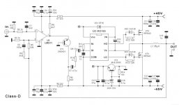
the thing i found interesting in this amp is that it requires original tl074/084 and bc327 and bc337 . if you compromise in this area it will consume alot of current at idle an produce hf noise.
my question is can i use two lm339 instead of tl074/084 and which other transistor can i use to substitute bc337 and bc327 😕
vvv vvv my current project vvv vvv
hi all , i have made many pcb versions of this amp ,
i still stick to the original schematic in the above link.
the thing i found interesting in this amp is that it requires original tl074/084 and bc327 and bc337 . if you compromise in this area it will consume alot of current at idle an produce hf noise.
my question is can i use two lm339 instead of tl074/084 and which other transistor can i use to substitute bc337 and bc327 😕
vvv vvv my current project vvv vvv
Are this pcb with smd tested and working?
hi all , i have made many pcb versions of this amp ,
i still stick to the original schematic in the above link.
the thing i found interesting in this amp is that it requires original tl074/084 and bc327 and bc337 . if you compromise in this area it will consume alot of current at idle an produce hf noise.
my question is can i use two lm339 instead of tl074/084 and which other transistor can i use to substitute bc337 and bc327 😕
vvv vvv my current project vvv vvv
I uploaded This gerber files to JLP pcb,but they say it is no drill files.
Could this be fixed?

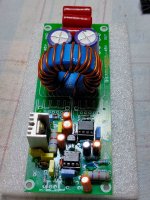
I made new Gerberfiles from this....hello all , i have made my latest version of this amp , i opted for a through hole ic due to challenges in getting a geniune tl074/84 smd . imagine the smd also have issue 🙁,
A not original ic works fine in preamp,eq, crossovers etc , but can't work well in this class d amp ,
with this amplifier it works but the amp produces a lot of hf . but when i use a good geniune ic the hf noise reduces and the amp does not draw a lot of current
but a geniune tl074/84 works with no issues at all .
here is my project and pcb files . have fun fam 😀😀
You don´t happend to have a sketch on the komponent placing (SMD) on the underside.
I cant see all komponens descriptions...
I cant see all komponens descriptions...

modification to use 2 N-ch mosfet
I have not built, but in simulation it works
Passive discharge will not fast enough.
Ad one more PNP bjt
I seem no decouping on the 12V rail for the IR2153, and that bootstrap cap needs to be MLCC ceramic, not electrolytic. 10uF is much higher than needed, 1uF ceramic will be plenty - make sure the decoupling for the IR2153 is also ceramic and at least 10 times the value of C10Anyone tried this😀
Will test today to see if it works😉😉😉
hi, yes, it works power reaches 300 watts at 4 ohms, conducted tests at 2 ohms works well, but the power characteristics are not removed . and yet it is this amplifier that is more suitable for a subwoofer it is not suitable for a wide band .
ir2153 classd
Will test today to see if it works😉😉😉
hi andrew below is a link to the amp working in fullrange. i just wonder if it can support 2+ ohms load at +/-70vlts?Setup didnt work
also another channel showing that it is working
Last edited:
you can experiment...I'm not convinced C8 at 1nF makes sense. Probably it is there to quench HF oscillation, but a crispier solution would be to simply connect something like 10pF from the collector of MJE350 to pin 2 of LM311.
no, I don’t have such a source, but it works well at + -49 volts, I’ll note again that the amplifier for a wide band is not very good, but it’s quite suitable for a subwoofer. As soon as I have a + -75 source, I will definitely conduct an experiment I'll post the results if someone doesn't beat me to it.ave you ever tried it at +/-75 volts ????
do you still need gerber files compatible with jlcpcb ?I made new Gerberfiles from this....
- Home
- Amplifiers
- Class D
- Ultra Simple Class D