The cheap, stereo input version of the design. The power supply can be integrated or separated at the +/-15v rails.
The MC/MM switch goes out the back and can be board mounted or panel mounted. The load switches are not representative of the actual parts (we don't have the full CAD models at present) and the output relay is not shown, although the board location is visible.
The board has been ordered, and the parts are in stock.

I have been simulating the noise of the circuit in the 1Hz the 100Hz range and it seems that in this area the noise could be reduced. If the input 1uF cap is replaced with a jumper, the input FET calibration circuit removed (OPA202 and support), and a 10mF cap placed between the FET sources and 5.1 ohm/1k feedback the noise drops significantly. See attached schematic and noise result. I also replaced the 1.2k current sink with a compliant current source exactly like the one in the drain circuit but that was not a change made for noise reasons, it was for current stability over Vgs variations. There were no changes in THD with these changes. After these changes the Q on the 3.5Hz filter seemed a little too high so I change the 330k to 300k to lower the Q. I simulated with 2SK209GR, LSK170B + 10 ohm source resistor and three jfe2140 pairs. The circuit behaved well, the only requirement on the FET is that the source voltage is higher than the gate voltage at ~2.2mA. The LSK170 and jfe2140 had better noise performance but worse distortion, so it seems the 2SK209GR is already the best choice. I understand that 1) Spice simulation results have little meaning and it needs to be prototyped to verify the results. 2) The 1Hz to 100Hz range may not be a critical noise consideration, but that range is where the circuit gain is the highest so it would seem that any noise reduction would be welcome. Please feel free to comment and educate me. My comments are meant for my understanding and not criticism. The blue line is the original circuit, and the yellow line is after the changes. I changed the OPA1656 in the RIAA section to LM4562 to get the circuit to simulate. The 220n and 5.1 Meg time constant causes the simulation to fail. Replacing the OPA1656 with a LM4562 fixed the DC failure. This change was not a noise consideration, I expect the OPA1656 to have lower noise. Spice is so much fun.
Attachments


So, you did exactly what the circuit was intended to avoid (the need for a 10mH cap) and got the expected result.
Good job with the Spice.
The OPA1656 model is certainly not the best thing that TI has ever done. It has really dodgy convergence issues.
By the way, the actual circuit works just fine in practice, and the "1/f" noise is not a practical problem.
I'm in the process of testing the new unit, but life has got in the way (a month-long trip to Japan, multiple computer failures and replacements etc. etc.) and hope to have some results shortly.
The unit is alive! It's not in a case, so hum is an issue (as expected), but with either an external +/15v bench supply or the on-board linear regulator the hum is almost pure 60Hz and is c 1mv p-p with the board sitting on top of a grounded steel plate with an insulator in between.
All the functions seem to operate with no sign of oscillations or other pathological behaviors.
There was a minor soldering issue on one IC, but that was readily diagnosed and corrected, so the construction work was excellent.
The additional output protect circuitry seems to work as expected, with no rail-to-rail output excursions even with the supply plug pulled randomly, so that's good.
I'll try to do a cursory spec test, then attempt to put it in a case for the full set of tests.
Test setup, with the 60Hz output noise snapshot on the screen. 80ms/dev, 1mv/div. MC standard mode, no extra gain . DC offset <1mv.
As you can see the on board linear supply is in use. Using a bench supply makes no difference. The 60Hz noise can be attenuated by changing the orientation of the board, or adding more shielding on top.
Long term output snapshot over 80s! No significant LF "wobbles", max about +/-2mv. I've tried changing the sweep times to capture various frequency ranges, but it still remains within about +/-2mv, as long as I'm not waving my hands close by.
I've checked the gain and RIAA compliance coarsely and they seem close to what was expected.
Changing to MM mode changes the signal as intended.
Do you really want a critique on the design changes? Perhaps a PM exchange might be better?I have been simulating the noise of the circuit in the 1Hz the 100Hz range and it seems that in this area the noise could be reduced. If the input 1uF cap is replaced with a jumper, the input FET calibration circuit removed (OPA202 and support), and a 10mF cap placed between the FET sources and 5.1 ohm/1k feedback the noise drops significantly. See attached schematic and noise result. I also replaced the 1.2k current sink with a compliant current source exactly like the one in the drain circuit but that was not a change made for noise reasons, it was for current stability over Vgs variations. There were no changes in THD with these changes. After these changes the Q on the 3.5Hz filter seemed a little too high so I change the 330k to 300k to lower the Q. I simulated with 2SK209GR, LSK170B + 10 ohm source resistor and three jfe2140 pairs. The circuit behaved well, the only requirement on the FET is that the source voltage is higher than the gate voltage at ~2.2mA. The LSK170 and jfe2140 had better noise performance but worse distortion, so it seems the 2SK209GR is already the best choice. I understand that 1) Spice simulation results have little meaning and it needs to be prototyped to verify the results. 2) The 1Hz to 100Hz range may not be a critical noise consideration, but that range is where the circuit gain is the highest so it would seem that any noise reduction would be welcome. Please feel free to comment and educate me. My comments are meant for my understanding and not criticism. The blue line is the original circuit, and the yellow line is after the changes. I changed the OPA1656 in the RIAA section to LM4562 to get the circuit to simulate. The 220n and 5.1 Meg time constant causes the simulation to fail. Replacing the OPA1656 with a LM4562 fixed the DC failure. This change was not a noise consideration, I expect the OPA1656 to have lower noise. Spice is so much fun.
Both channels are mostly working correctly, including the warp and mono functions. The basic MC/MM gain is c. 54/34 dB. The various mode delta gains are as expected. The "unplug the supply while the unit is operating" DC excursion is higher than expected at c. 3v peak, but this is seemingly due to the control voltage on the relay on/off FET gate being higher than expected at 10v rather than being clamped at 4.7v, so it needs to be looked at.
I can also get 10-20dB lower 60Hz hum by putting a second grounded metal plate over the board, so it's probably worthwhile doing some distortion etc. testing even without the unit being in a case.
I can also get 10-20dB lower 60Hz hum by putting a second grounded metal plate over the board, so it's probably worthwhile doing some distortion etc. testing even without the unit being in a case.
No, a review of the design changes is not needed, but thank you for the offer. I am very interested in getting a blank board when you reach that point. The design is interesting.
New low cost board with integrated PSU with the two boards still physically connected and supplied from an AC out wall-wart.
Distortion essentially unchanged, hum reduced somewhat when compared to the previous board.
The top plot is the ADC/DAC in loopback with +6dBv signal levels.
The attenuator remains at 51.4dB, so the gain is 55dB for the nominal MC input.
I'll post more as opportunities occur.
All plots 1/12 octave smoothing, 4 averages.

MM mode RIAA compliance. c. 20mdB of error 20Hz-20kHz.

MC mode RIAA compliance. c. 20mdB of error 20Hz-20kHz

Maximum gain RIAA compliance essentially unchanged.

Warp filter in "stereo" mode. Not really stereo as only one channel is driven as I don't have a complementary source.
The response is as expected. For a true stereo signal the attenuation would be c. 20dB at 10Hz and 33dB down at 2Hz.

In true mono mode. The LF response has a larger RIAA compliance error due to the relatively imprecise RC components used in the warp network.
I believe that the design has now been validated. Bill Hirsch has agreed to produce a production worthy board.
MM mode RIAA compliance. c. 20mdB of error 20Hz-20kHz.
MC mode RIAA compliance. c. 20mdB of error 20Hz-20kHz
Maximum gain RIAA compliance essentially unchanged.
Warp filter in "stereo" mode. Not really stereo as only one channel is driven as I don't have a complementary source.
The response is as expected. For a true stereo signal the attenuation would be c. 20dB at 10Hz and 33dB down at 2Hz.
In true mono mode. The LF response has a larger RIAA compliance error due to the relatively imprecise RC components used in the warp network.
I believe that the design has now been validated. Bill Hirsch has agreed to produce a production worthy board.
Last edited:
I just have to add the v-score or mousebites to make PSU removable. Then I'll send it to JLCPCB for fabrication of another small batch. I'll build another one to verify the BoM (currently a Mouser project). Still haven't finalized any further/final testing requirements.
When it's finished, we'll have to find a way for distribution. I just won't have time to handle ordering and distribution.
When it's finished, we'll have to find a way for distribution. I just won't have time to handle ordering and distribution.
I'll test the board for functionality, including the improved power supply interruption protection circuit.
I'd offer to sell boards at cost up until the IRS mandated $600 limit, but that is prohibited by DiyAudio.
I'd offer to sell boards at cost up until the IRS mandated $600 limit, but that is prohibited by DiyAudio.
It's not clear to me how to do that as a non-traditional "vendor" who wishes to use Paypal.
Please enlighten me.
Please enlighten me.
As I understand, there are a couple of ways. If you head to Marketplace, Swap Meet, you'll see plenty of members selling stuff, including fairly large numbers of transistors, etc., which is apparently permitted because the sellers aren't "Commercial". Paypal or other payment methods are allowed.
For commercial vendors who want to advertise products, they must register as Vendors, but for you developing a project and making it available, I can't see how that differs from many others doing the same in this Forum. To be sure, however, I'd ask @Jason for clarification.
The second way is Marketplace, Group Buys. There is a helpful sticky on tax implications: https://www.diyaudio.com/community/...dinator-tax-implications.408864/#post-7593926. There are a lot of projects offered here for which the boards are offered as Group Buys. That's how I did it for your earlier projects on AK, though the rules are seemingly different there.
Group buys are getting fairly onerous, between IRS, PayPal fees and the time required for distribution. Making the gerbers available allows close groups of people to make it happen.
I agree with the former, but not sure how one makes gerbers available only to close groups of people yet still distribute them. Can you elaborate?
The following worked for me. It allowed anyone to purchase PCBs, yet no buyer ever sees or accesses the Gerber file, and the "seller" (me) never had to touch boards or pack boxes or do anything at all related to shipping.
It was for a PCB called RACAM - Round Amp Camp Aamp Monoblock - and here is a (link) to its purchase thread. Worked well IMO. By the way, RACAM is now obsolete and a new, bigger, rounder Monoblock amp has taken its place. Sold and shipped by another member, not me.
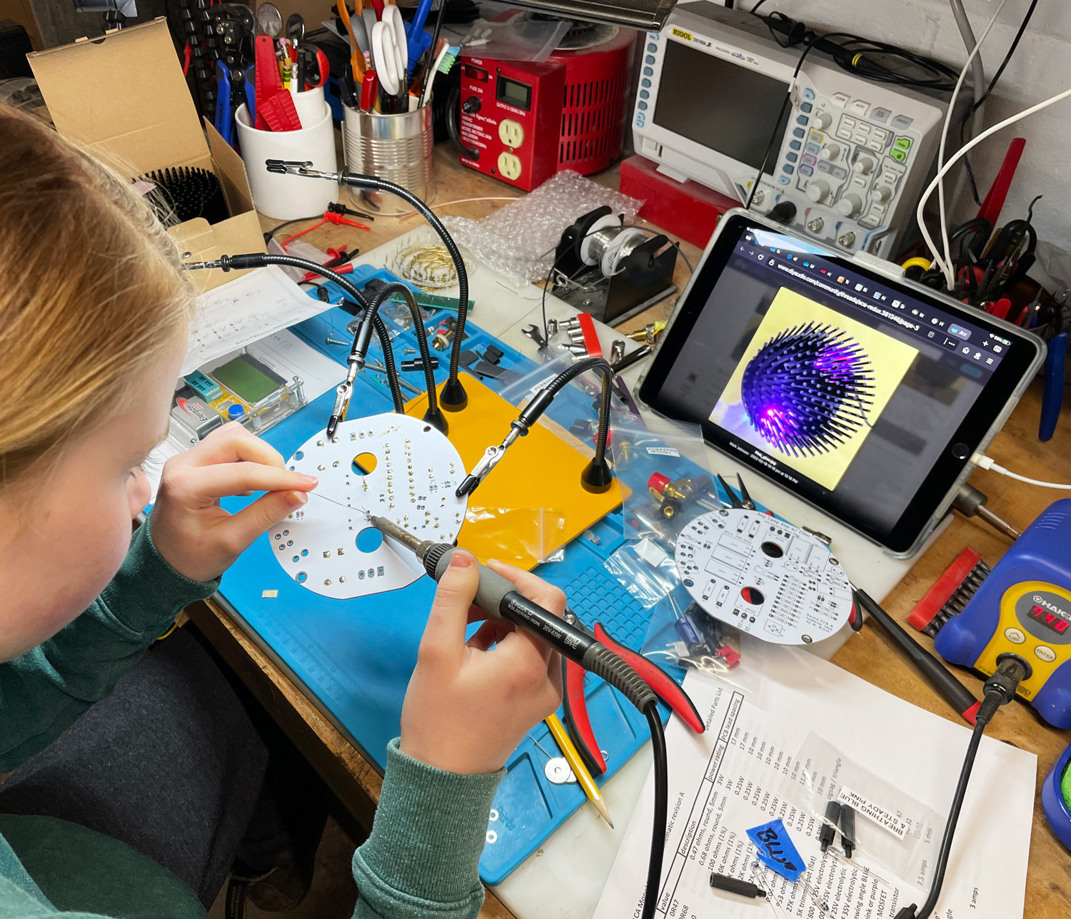
Here's an adorable photo of member @pfarrell 's 11 year old daughter, assembling a RACAM. On her tablet screen at right you can see the Hedgehog heatsink with up-firing pink LEDs.
- PCBs available in multiples of (quantity=5) ONLY ; minimum order 10 pieces
- Send me a diyAudio Private Message with your quantity desired and your ship-to address
- I'll put that into the Fab's price quote system and get you a price quote including shipping and Prepaid VAT (where available)
- If you approve the quote, send me the money by PayPal
- When I receive your money, I'll send the secret Gerbers to the fab, place the order, pay for the order with my own credit card, and provide your ship-to address
- Fab builds the boards and notifies the customer (me) when complete, then ships to the buyer's ship-to address. Fab tells me the tracking number
- I message you saying boards are done and shipped to you, here's the tracking number
It was for a PCB called RACAM - Round Amp Camp Aamp Monoblock - and here is a (link) to its purchase thread. Worked well IMO. By the way, RACAM is now obsolete and a new, bigger, rounder Monoblock amp has taken its place. Sold and shipped by another member, not me.
Here's an adorable photo of member @pfarrell 's 11 year old daughter, assembling a RACAM. On her tablet screen at right you can see the Hedgehog heatsink with up-firing pink LEDs.
Last edited:
I am aware of the indirect approach. I previously rejected it as it forced the potential builder to purchase multiples of 5 boards and to cover the entire cost of shipping from China. I didn't find this to be reasonable when I was, essentially, using them as guinea pigs, expecting them to report their impressions.
As it turns out that was (mostly) a forlorn hope...
I don't care about any proprietary aspects of this, so providing the Gerbers is still an option.
As it turns out that was (mostly) a forlorn hope...
I don't care about any proprietary aspects of this, so providing the Gerbers is still an option.
- Home
- Source & Line
- Analogue Source
- Ultra high spec opamp MC/MM phono, warp "elliptic" filter, line, headphone amps