Finally, I collect enough information to design such a REAL R-2R attenuator.
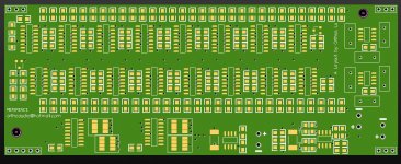
Fully balanced attenuation through 16 bit R-2R resistor network.
65535 steps current attenuations available, two Ultra low-noise low distortion OPAMP AD797AR were used as I/V convertor, the same structure as the module in Mark Levinson's No.32 ^_^
Considerate LAYOUT, 4-LAYERS PCB with 2 Oz copper,thanks Mark ^_^
Considerate POWER MANAGEMENT, onboard ultra-high performance linear regulator
High-precison SMT chip resistors
Simple data interface for micro controller
dimension:5545mil*2135mil
current switches: DG413DY, ultra precision analog switches
I/V convertor : AD797AR, ultra low-noise,ultra low distortion OP from ADI
Onboard regulator:LT1355
Resistors : YAGEO RT series @ 1% tolerance
The PCB will arrive next week, I will assemble the whole module and test then.
Anyone interest in it? ^_^
Attachments
If you have 65535 steps and an R-2R ladder, you need far better than 1% tolerance resistors. You need 0.001%. I've no idea where you'd get such things.
If you have 65535 steps and an R-2R ladder, you need far better than 1% tolerance resistors. You need 0.001%. I've no idea where you'd get such things.
we don't need such high precision resistors up to 0.001%, 1% is enough in this application. even though, Mark Levinsion's product uses 5% resistors in their module in No.32, 1% resistors in No.320s/326s ^_^
We don't need a tolerance = 1/65535=0.00001526 in each step, just think about the R-2R DACs like PCM1704U-K ^_^
You might not need 0.001%, but you do need better than 1% if you want to keep the errors down and make the accuracy reflect the precision. I'm assuming you don't actually make all those 65535 steps available to the user, but actually code for a logarithmic law and pick codes that give 1dB steps. At 6dB of attenuation, 1% resistors give an uncertainty in attenuation of 1.4%, and between channels of 2%, or 0.2dB. Stepped balance controls typically go in steps of 0.25dB, so those 1% resistors could cause balance error of one balance step. I don't see that a stepped attenuator is entitled to any balance errors, so whilst 0.001% isn't necessary after all, I think you need better than 1%, and 5% is certainly not good enough.
i find it rather strange that mark levinson would use 5% tolerance resistors in the precision attenuator in such a flagship product as the no.32 preamp.
are you sure about your source of information?
mlloyd1
are you sure about your source of information?
mlloyd1
we don't need such high precision resistors up to 0.001%, 1% is enough in this application. even though, Mark Levinsion's product uses 5% resistors in their module in No.32, 1% resistors in No.320s/326s ^_^
We don't need a tolerance = 1/65535=0.00001526 in each step, just think about the R-2R DACs like PCM1704U-K ^_^
At 6dB of attenuation, 1% resistors give an uncertainty in attenuation of 1.4%, and between channels of 2%, or 0.2dB.
How did you figure that? I get more like .01db.
10 log 100= 20, for 2% error: 10 log 102=20.09 or .09db error, for 5% 10 log 105=20.21 or .21db.
So the 1% tolerances are fine and even the 5% would be fairly inaudible.
i find it rather strange that mark levinson would use 5% tolerance resistors in the precision attenuator in such a flagship product as the no.32 preamp.
are you sure about your source of information?
mlloyd1
Hi mollyd1,
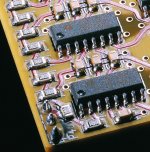
I just download the image from Mark's website and found this >_< But I'm not sure all the version of different date manufactured module uses the same 5% resistors
regards
bbp
Attachments
You might not need 0.001%, but you do need better than 1% if you want to keep the errors down and make the accuracy reflect the precision. I'm assuming you don't actually make all those 65535 steps available to the user, but actually code for a logarithmic law and pick codes that give 1dB steps. At 6dB of attenuation, 1% resistors give an uncertainty in attenuation of 1.4%, and between channels of 2%, or 0.2dB. Stepped balance controls typically go in steps of 0.25dB, so those 1% resistors could cause balance error of one balance step. I don't see that a stepped attenuator is entitled to any balance errors, so whilst 0.001% isn't necessary after all, I think you need better than 1%, and 5% is certainly not good enough.
Of course we don't need all the 65535 steps in the actual application,I plan to make the attenuations adding 0.1 dB/step from -96dB to -46dB and 1 dB/step from -46 to 0 dB.
That means I need to calculate the relationship for decimal/dB >_<
For the tolerance, 0.1dB is equal to 1.14%
How did you figure that? I get more like .01db.
10 log 100= 20, for 2% error: 10 log 102=20.09 or .09db error, for 5% 10 log 105=20.21 or .21db.
So the 1% tolerances are fine and even the 5% would be fairly inaudible.
No, I'm afraid your calculations above are incorrect. A 1% error would mean that the attenuation was 0.99 or 1.01 of what it ought to be. Further, 10 log is for powers, but potential dividers deal with voltages, so we use 20 log. Taking the 0.99 case, 20 * log(0.99) = -0.087dB - near enough 0.1dB.
No, I'm afraid your calculations above are incorrect. A 1% error would mean that the attenuation was 0.99 or 1.01 of what it ought to be. Further, 10 log is for powers, but potential dividers deal with voltages, so we use 20 log. Taking the 0.99 case, 20 * log(0.99) = -0.087dB - near enough 0.1dB.
Acutally divides current ^_^
Member
Joined 2002
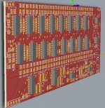
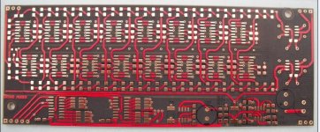
PCB arrived !!!
Looks nice! I like the color, when are you going to start the project ?
Looks nice! I like the color, when are you going to start the project ?
well, the main components of the project will arrive this two days, I can assemble one or two module and send them to have a Audio Precision Test.
then, I will start the software for MCU part.
maybe a simple LCD1602 and two rotary encoder will be added to the MCU part
a female board is needed,if we want to configurate the module as a preamplifier, which provides DC supply +/-15V and 8 or more signal relays for the input source selection
^_^
Member
Joined 2002
well, the main components of the project will arrive this two days, I can assemble one or two module and send them to have a Audio Precision Test.
then, I will start the software for MCU part.
maybe a simple LCD1602 and two rotary encoder will be added to the MCU part
a female board is needed,if we want to configurate the module as a preamplifier, which provides DC supply +/-15V and 8 or more signal relays for the input source selection
^_^
Interesting,
How many input's are you planning ? Say maybe 5-6? Maybe you can add a led per input, so when that input is on, the led lights up.
Possible to do something similar to the volume. ? A led per hand full of steps. example 100 steps, you get 10 led's ( small ones tho 🙂
Ld's are becoming so common for projects, but led's for visual volume & input would be sleeker.
Myst some ideas 🙂
J'
thanks for the suggestion J‘ 😀
maybe a nice VFD display can be used for information display, volume satus,the source etc
remote is also a regular function for a preamplifer/attenuator
Member
Joined 2002
thanks for the suggestion J‘ 😀
maybe a nice VFD display can be used for information display, volume satus,the source etc
remote is also a regular function for a preamplifer/attenuator
No, i said NO DISPLAY, read what i said 😱 all these volume projects use a display, how about NOT using one on this one, and using my ideas with the led per input JUST one led per input selected, and for the steps, example 100 steps, you have 10 led's 1 per 10 steps.
J'
No, i said NO DISPLAY, read what i said 😱 all these volume projects use a display, how about NOT using one on this one, and using my ideas with the led per input JUST one led per input selected, and for the steps, example 100 steps, you have 10 led's 1 per 10 steps.
J'
yeah, display may cause some noise problem in most applications
Member
Joined 2002
yeah, display may cause some noise problem in most applications
sure, but my suggestion was nice too,! no lcd or vfd.
Make sure you take some pictures of building progress.
J'
- Status
- Not open for further replies.
- Home
- Group Buys
- Ultra high precision Volume module like Mark Levinsion's