While waiting for the new boards to arrive, I got my power supply build and tested. Well, a quick test anyways - no magic smoke released. This was a test to ensure it all works before buying the chassis. This should all fit into a 300mm deep, 2U, rack width chassis.
It's a dual mono CRC PSU with:


It's a dual mono CRC PSU with:
- Each PSU based on DIYAudio store Power Supply. It has 15,000uF x 2 per side per rail.
- Dual Mono Ground Loop Breakers
- Mains DC blocker (based on Bonsai's iSSDCB)
- Control Circuits
- Always-On 12V SMPS for control circuits
- Momentary switch driver (based on Rod Elliott's P166)
- Soft Start (based on Rod Elliott's P39)
- 12V Trigger (based on Rod Elliott's P156)
- Thermal Interrupter (uses an external LM35DT circuit - Bob Cordell inspired)

Quick update: I have parts on order for the new test build. I'm hoping to have this complete within the next 2 weeks. Once (or if) it checks out, I'll release boards to those that have expressed interest.
Hi Chris,
I'll add you to the list. I'd like to build and test the amp board before releasing them.
Same with the PSU. I need to some more testing on it to ensure it's working. Especially with mains voltage on the PCB. Proceeding carefully. If there's interest in the PSU, I can start a new thread discussing it. Also, I designed the PSU for my own use with 120V mains. I need to look at the design again to see if it will work as designed with 240V mains.
Couple of quick questions Brian,
- Did you increase the diameter of the C1 through holes from the previous pcb?
- Is the input header J1 mislabeled? (+DC,+AC,-)
Hi @Vunce,
I did correct the pad size issue on this version. The pads have a 1.1mm hole and will accommodate caps with a footprint up to 42mm x 20mm and a pitch as big as 37.5mm.
The input connector is labeled corrected. It is accommodates a 2 or 3 position connector in 5mm or 2.5mm pitch. The idea for 3 position is to allow for a switch on the rear panel to bypass the input couple cap for a DC coupled input. Take a look at post #142 for more info.
It's interesting... I think the attraction is from the simplicity of the core circuit. But this is also what makes the tuning challenging. It's more sensitive to part parameters. The trade-off for simplicity. Fun project though. Can't wait to till we have several different builds out there to see what people actually think of it.
@StevenCrook @brian92fs
I will now take a look at the circuit in Post 194.
It sure has come a long way from my version.
Of course the main circuit is like the original, but they say the devil is in the details.
I will now take a look at the circuit in Post 194.
It sure has come a long way from my version.
Of course the main circuit is like the original, but they say the devil is in the details.
Hi lineup, the input drain resistors R8/R9 are dependent on the VAS device uses AND the gain of these. My models have a gain of 115 to 125. If the gain is outside of this, you need to alter the resistor values to get the same VAS current. I am targeting for 20mA.
I’m working on an updated guide that will have a table of resistor values to use with different gains.
I’m working on an updated guide that will have a table of resistor values to use with different gains.
Test build is getting closer. I missed one pot in my parts order (VR1), so it'll be at least several more days while I wait for that to arrive. Which give me time to get my heatsinks tapped.
I'm using 330U for the feedback cap C3. The 220u and 330u caps are the same footprint and about the same price, so I elected to use the larger cap.
With the lower pole from C3, I'm using a WIMA 4.7U MKP4 for C1 and 100k for R2. Probably an overkill.

I'm using 330U for the feedback cap C3. The 220u and 330u caps are the same footprint and about the same price, so I elected to use the larger cap.
With the lower pole from C3, I'm using a WIMA 4.7U MKP4 for C1 and 100k for R2. Probably an overkill.
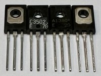
For the VAS devices, I managed to source a large supply of Sanyo 2SC3503E and Fairchild 2SA1380E. These are the lower voltage versions of 2SC3503/2SA1381 with a 200V Vce rather than 300V.
Authenticity on NOS parts is always a concern. The Fairchild 2SA1380E were from a authorized distributor. The Sanyo 2SC3503E were from a reseller out of Taiwan. I tested a sampling from each for gain and breakdown voltage. They seem to be authentic. Gain is in spec (range of 120 to 200) and Breakdown voltage is measuring in the 250V to 300V range.
I've found that these lower voltage parts have a higher median gain. The SC3503E / SA1381E I have on hand all test with a gain in the 115 to 125 gain and not much variability. Two-thirds of these 2SC3502E / 2SA1380E are testing in the 140 to 150 range with some of the N channels measuring over 200.
I plan to use these in the build as a final test for authenticity. If perform well and can hold up to 20mA and 700+mW of dissipation, I'd say they are authentic.
If they check out, I have enough of these to make them available to builders if there's interest.
Attachments
Forgot to mention, the gain was tested initially on a cheap Mega328 transistor tester. It was validated in a constant current test at 10mA with a Vce of 10V.
While I wait for parts, here’s some photos of the inductor and the jig I used to form it.
I used a one of those plastic spacers you get with your the TV Wall Mount kit as the former. It's a packet of various bolts and spacers you get when buying a mount. The spacer I selected is 16.6mm in diameter and 12mm thick. I mounted it with a washer on the end that I cut a slot in to hold the wire and then wound it. To hold it together, I used some 3/4 inch heat shrink tubing I got off Amazon. I end up with 11 to 12 turns. After the tubing shrinks, the outer turns are not captured by the heatsink. I peel these off and bend the leads down, then sand off the enamel. I end up with a inductor of about 9 turns for an estimated inductance of 1.35uH and a lead spacing of 10mm. And the heat shrink keeps it tightly wound.


I used a one of those plastic spacers you get with your the TV Wall Mount kit as the former. It's a packet of various bolts and spacers you get when buying a mount. The spacer I selected is 16.6mm in diameter and 12mm thick. I mounted it with a washer on the end that I cut a slot in to hold the wire and then wound it. To hold it together, I used some 3/4 inch heat shrink tubing I got off Amazon. I end up with 11 to 12 turns. After the tubing shrinks, the outer turns are not captured by the heatsink. I peel these off and bend the leads down, then sand off the enamel. I end up with a inductor of about 9 turns for an estimated inductance of 1.35uH and a lead spacing of 10mm. And the heat shrink keeps it tightly wound.
If you aren't interested in creating the inductors yourself, the boards will accommodate Tom's (@tomchr) 1.1uH inductors available from Neurochrome.
My first test build was constructed with these to ensure they fit.

My first test build was constructed with these to ensure they fit.
- Home
- Amplifiers
- Solid State
- Ultra Amplifier Build Thread