I have all the parts and chassis now. And I'm finally getting over the Flu. Going to try to get it up an running this weekend... fingers crossed.

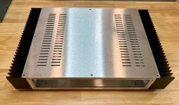
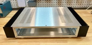
I figured I might get some questions on the chassis I'm using, so I took some pictures before it is stuffed.
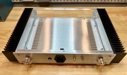
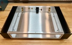
This is custom chassis built by Jin at par-metal.com. It is a customized version of their 20-series chassis designed to accommodate Conrad Heatsinks MF30-75 flat backed heatsinks. Jin also fabricated the back panel for me - much cheaper than Front Panel express if your OK without the text engravings. Jin has the CAD files for this now, so I'm guessing others could order it as well (chassis only. I ordered the heatsinks direct from Conrad).
I plan to use Front Panel Express for the front panel, once I figure it out.
Some may object to the lack of symmetry on the back panel. I positioned the inputs next to each other based on advice from Andrew at HiFiSonix (@Bonsai). He has some excellent article on grounding and recommends placing the inputs next to each other with their grounds connected and tied to the chassis through a small capacitor. This layout facilitates that.
Now onto tapping the heatsinks...
Attachments

Another delay... got the heatsinks tapped yesterday and the PSU wired in. When to solder in the VAS transistors and found I am out of insulators. Put an order in with Mouser.
So, hopefully I'll be able to power it up next weekend.
So, hopefully I'll be able to power it up next weekend.
BTW - I switched to thread forming taps this time instead of thread cutting taps. Way easier to use and clean up. Wish I had "discovered" these sooner.
I sprung for higher quality taps from McMaster-Carr. That probably helped as well.
I sprung for higher quality taps from McMaster-Carr. That probably helped as well.
Why do you use a Vbe multiplier transistor (Q9) for temperature compensation?
With the lateral Exicon MOSFETs it is not necessary, since they have a negative temperature coefficient and are thermally self-stabilized
With the lateral Exicon MOSFETs it is not necessary, since they have a negative temperature coefficient and are thermally self-stabilized
Hi adiaz
AFAIK..it is the transistor to set the bias current for the output MOSFET with span the voltage between the gate of them with the trim pot.
kr
chris
AFAIK..it is the transistor to set the bias current for the output MOSFET with span the voltage between the gate of them with the trim pot.
kr
chris
Hi adiaz,
Refer to posts 183 to 186. I found that the bias current was sensitive to ambient temperature changes. This was confirmed with my test build. Using a transistor to sense ambient temp changes resolved this in simulations. I will try to validate on the bench.
With my first test build, it was constructed originally in the summer (100F+ garage temp) and then reassessed in the fall when ambient temps had dropped into the 60 - 70 range. We now approaching winter here, so my garage should be in the low 50's. I can set the bias there then move it into the house to see what a 20F ambient temp swing does to the bias.
In the room where I listen to my equipment with the amplifier there is usually not much difference in temperature throughout the year.
In summer I turn on the air conditioning and in winter I turn on the heating. If the room where I listen to music is very cold or very hot, I do not listen to music.
In summer I turn on the air conditioning and in winter I turn on the heating. If the room where I listen to music is very cold or very hot, I do not listen to music.
I can understand your perspective. However, I would prefer the design to be stable with regard to ambient temperature. Switching to a transistor based biasing network seemed like a reasonable change from my perspective.
If a builder wants to use a resistive biasing network, they are free to modify it and stuff the boards that way.
If a builder wants to use a resistive biasing network, they are free to modify it and stuff the boards that way.
Whenever I rechecked my Exicon-made amps, the bias current always stayed where it was set from the beginning. I never got variations (must be the room temperature was the same, heh heh).
In fact, the most important thing for me in using exicon is precisely not having to use an extra transistor screwed to the heatsink and knowing that they are very safe from thermal runaway.
By the way, a small capacitor between the collector-emitter pins in Q9 would be good to improve the high-frequency response and stabilize a little more the possible small rapid voltage variations in the gates of the mosfets.
Other Lateral MOSFET designs don't seem to have an issue with ambient temp stability. I think the lack of drivers and high VAS current make this design more sensitive to ambient temp changes.
Note that the bias transistor (Q9) in this design does not mount to the heatsink to sense the output device temp. It mounts on the board in free-air to sense ambient temp. I choose 2N5551 specifically because it seems to work best (in sims) to compensate for ambient temp changes.
I am choosing to build it this way. But as I mentioned earlier, each builder it free to build it however they like. It will work with a resistive network, at the expense of some sensitivity to ambient temp changes. As you pointed out, this may not be an issue for some builds.
I also never mounted "extra" drivers for the mosfets (VAS direct). And the bias current of the VAS that I normally use is 12-15mA, but even if I choose 20 or 25mA (for me unnecessary) it would not affect the bias current of the mosfets either.
Keep in mind that I built dozens of amplifiers with Exicon mosfets. All in correct operation since the first day, the first one has continued working for 20 years without any problem, with the bias always at the same value. In practice I never experienced a bias value change with these misfets, I hope you can check it in reality without Q9.
Keep in mind that I built dozens of amplifiers with Exicon mosfets. All in correct operation since the first day, the first one has continued working for 20 years without any problem, with the bias always at the same value. In practice I never experienced a bias value change with these misfets, I hope you can check it in reality without Q9.
Ah, another very important thing.
It is useless to have put extra electronics to improve the power supply rails if the GND is not wired correctly inside the amplifier.
The GND routing, the design of the power supply and the placement of the components are crucial to achieve very quiet amplifiers. It took me years to get the right recipe, I am very critical of that, for me it is essential that there is no audible background noise when approaching the speaker. The RCAs do not have to be together to achieve this, nothing to do with it.
Another typical problem is the mechanical vibration noise of the toroidal transformers, this depending on the manufacturer is more likely to occur than others, and it is also an annoying problem. A long time ago I bought from a manufacturer that makes magnificent transformers and they are perfect, but in some old ones that presented these problems I filled the inside of the ring with epoxy resin and it was mitigated to 80%.
Hi
please confirm
For fast switch of i read in post 822,894,939 that it is needed that the extra pcb has to be soldered just D1, D2 a 22µF cap and a LED with resistor and connect J2 to the secondary of the transformer
J3 to one channel at the connector X1 SSR
J4 to the other channel at the connector X1 SSR
in post 947 is written that the COM at a secondary without center tap has not to be connected
kr
chris
Hi adiaz,
I agree that grounding layout it very important. This design uses the same grounding approach as the wolverine project. I spent a lot of time with the PCB design to refine this. The initial test build was completely silent. I heard nothing with with my ear right up against the speaker. Having said this, noise issues can be influenced by the environment. We'll need more test build to confirm the initial results.
The transformers and power supply I am using do not exhibit any hum or vibration issues. I am using a PSU with a DC blocker, which should help with this. The transformers are dual 160VA Avel Lindbergs. A dual bridge rectifier to help with any imbalances in the transformer windings would probably also help, but I ran out of room to fit this.
As I mentioned earlier, my first test build used a resistive bias network. It operated fine except for ambient temp sensitivity. I choose to use a transistor based bias network to address this. I made this change based results of simulations that were confirmed by bench testing. I understand that moving to a transistor based bias network has tradeoffs. It adds complication and introduces an new failure point. The tradeoff is worth it in my opinion.
I realize some will not think this is necessary. However, it is nearly impossible to create a design that pleases everyone. For every element I add or remove, someone will disagree. I'm doing the best I can and trying to offer flexibility to suit the inclinations of individual builders. Any elements that are not required for operation are identified in the build guide as optional components.
I do appreciate the feedback. I hope I'm not coming across as dismissive. I enjoy the conversation and debate.
My advice is to make a design thinking only of your needs. Sharing it is enough to help others. It is clear that everyone can freely do whatever they want.
At the time I got a lot of help from people who had more construction experience than me. and my experience today tells me that the simpler the project is, the more reliable it is.
I think Mr. Einstein said "make things as simple as possible, but don't limit yourself to the simple"
PD. I don't find your answers derogatory at all, I hope mine aren't either. My intention is just to help, I built many amplifiers exclusively with these Exicon mosfets for 20 years.
Got it put together and powered up. No smoking parts, but there's an error in my build somewhere. Rails power up OK, but the VAS is running very low current and there's full positive rail voltage on the output. I spent a few minutes poking around but haven't located the issue.
I'll try to commit some real time today or tomorrow to do the typical troubleshooting. Looking for bad or missed solder joints and confirm I didn't mix up a transistor gender somewhere. I'm assuming this is an error I made and not an issue with the board itself... but we'll see.
I'll try to commit some real time today or tomorrow to do the typical troubleshooting. Looking for bad or missed solder joints and confirm I didn't mix up a transistor gender somewhere. I'm assuming this is an error I made and not an issue with the board itself... but we'll see.
- Home
- Amplifiers
- Solid State
- Ultra Amplifier Build Thread