Here are a couple shots of amps I'm running. These are all the way quiet...as in ear to the cone and no noise. Since the photos I have installed the safety ground from the ground pin of the ac inlet directly to the heatsink and from there connected to the power supply ground through a cl60 thermistor. The amps were equally quiet with and without this addition. In retrospect I might do a few things differently but I probably wont mess with what works.
Evan
No noise ?? You can't hear the input pair semi noise with your ear to the
tweeter ?
It's low > -110db .... but all of em' have it.
I can't imagine how Pass Labs gets a rated -120db ,
special semi's or something ?
OS
Yes it stops immediately. The servo isnt the cause I guess becauseAfter switching off or unplugging the amp it should play for a few seconds, does the hum stop?
You have removed the ground loops already and proven that the hum doesn't originate from the
transformer location. That leaves rail and/or ground noise or maybe the servo.
I can remove the IC from the socket and it did not change at all.
This is exactly what I'am analyzing right now... It can be that simply my PSRR is weak for a total silence...When this rectified "hum" reaches the amp , it's feedback/PSRR cancels
this out -just a simple "unregulated supply" - not perfect.
For more intolerant amps (CFA's) ,I added cap multipliers as an offset for this weakness.
Ostripper. my nx and sx amps are both CFA's and they are absolutely quiet - zero hum. The cap multiplier of course is a good solution, but it is not mandatory to get a quiet CFA 🙂
Cortez, if you really thicken up the 0V wire between your amp PCB and the PSU, does the hum level change?
Hypothesis: The PSU rails will have some ripple on them (depends also on quiescent current of the amp). On your amp you have decoupling capacitors. The decoupling caps essentially couple any AC ripple on the rails onto the 0V connection between the PSU and the amplifier board which will cause an IR drop across the cable - an example of common impedance coupling. If you look at Self, you will note that he recommends that you split the small signal 0V from the PSU decoupling capacitor ground for this very reason.
I think in many layouts you can get away with it (short thick ground cable), but it might be in your case that you cannot. So, I would test this out by thickening the wire up substantially and then listening to see if it makes a difference. Let us know, then we can take the next step.
Can you post your amplifier PCB layout as well?
If I look at your PSU PCB, it seems to fulfill the requirements for Teeing of the star ground. However, you may get some benefit by moving the amplifier ground connection further down the T - so after the oil caps.
Last edited:
Ok, then I'll try to thicken up my SGND PGND wire.
And also to take those last oil caps out for a test to see what their charging currents cause.
And you just gave me a good idea: I'll load my PS rails (both OPS & IPS separately) with
a dummy load to see which one increases the hum, this could be a usefull clue as well...
Wow, this whole thing is like a Poirot story chasing for the hiding bad guy... 😀
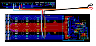
The IPS is on the previous PCB and the OPS I attach now.Can you post your amplifier PCB layout as well?
(The rails are wired with cables from collector to collector in the air.)
Attachments

Last edited:
I dont think taking the oil caps out will change anything - the value is quite small. The reason I propose you move your main ground futher away from the main PSU caps is to just make sure you are well away from any charging currents and potention IR drops on the copper PCB.
Yes, getting an amp quiet takes some sleuthing - even when you get all the basics right.
Yes, getting an amp quiet takes some sleuthing - even when you get all the basics right.
Can you measure the ripple voltage on the rails and output?
A simpler method could be to just add more capacitance to the PSU part.
Is the current demand so high that it is causing problems with the feedback or input ground?
A simpler method could be to just add more capacitance to the PSU part.
Is the current demand so high that it is causing problems with the feedback or input ground?
Can you draw this?Yes! The speaker GND wire goes to that GND point in the middle of the OPS PS section.
Is this correct? I tried to develop it correctly even 2-3 years ago when I made it... 🙂
From your description it sounds wrong, but I may be misunderstanding what you have typed.
Bill, ok - let me clarify
1. From the RCA to the amplifier PCB you run your screened cable in the normal way (screen plus signal). The 15 Ohm resistor is as I show on the amplifer PCB
2. From the RCA socket (which are still isolated from the chassis) ground connection, you run a bonding wire directly to the IEC earth
The ground loop now flows out to earth via the bond, and NOT through your amplifier PCB ground to the star ground.
I have tried the above technique and the ground lifter technique - both are very effective.
If you do not put the 15 Ohm resistor as I show, then you still run the risk that the earth loop flows through the amplifier PCB. If you still do not like the 15 Ohm resistor, then use a ground lifter between amplifier 0V and the chassis.
Hmm ok. Really not sure about that one. But I don't have ground loops, just hum, so don't need to worry about it.
How do you mean it? Which GND point and where to move?move your main ground futher away from the main PSU caps
Ripple: I just have DMM now.Can you measure the ripple voltage on the rails and output?
A simpler method could be to just add more capacitance to the PSU part.
Is the current demand so high that it is causing problems with the feedback or input ground?
More caps: maybe a C multiplier would be good for the IPS but its a bit more complex adjusment right now.
Currents: no, nothing special at all, normal class AB amp, Iq = 60-70mA / OP transistor.
See the attachment, thats how I wired my PS to OPS @ Speaker.Can you draw this?
From your description it sounds wrong, but I may be misunderstanding what you have typed.
Attachments
OK -I see what you have done here.
The decoupling is on the IPS board. The 0V to the IPS board caries both the small lsignal ground return and the decouple ground return.
No decoupling on the OPS from what I can see - can you confirm that?
I think you need to test as described above - looks to me like one of the issues could well be the common 0V line.
Last edited:
No noise ?? You can't hear the input pair semi noise with your ear to the
tweeter ?
It's low > -110db .... but all of em' have it.
I can't imagine how Pass Labs gets a rated -120db ,
special semi's or something ?
OS
OS, Don't you sleep?.... Yes a slight hiss from the tweeter...no hummm from the mid bass. The quietest amps I have built or used.
Yepp!No decoupling on the OPS from what I can see - can you confirm that?
And now I start the tests... 🙂
Much of the time most of the thermal noise isn't even from the LTP itself, but the current mirror and any other low-gain stages before the VAS, as well as the feedback resistors.
Bonsai: I should have been less stark, but it's hard to find a reason why the 15R resistor would do much good (unless they are bypassed by another wire to ground, but that doesn't reduce fault current). Even Bruno Putzeys in the article I linked to says they're no use. Obviously anything is possible, but in the case the resistor works without a redundant ground path I think it's important to model the entire ground system to find out what's going on.
Bonsai: I should have been less stark, but it's hard to find a reason why the 15R resistor would do much good (unless they are bypassed by another wire to ground, but that doesn't reduce fault current). Even Bruno Putzeys in the article I linked to says they're no use. Obviously anything is possible, but in the case the resistor works without a redundant ground path I think it's important to model the entire ground system to find out what's going on.
Last edited:
Keantoken,
no problem. I've built enough amps over the years to accept that there is no one perfect way of doing things.
I always fit a 'ground loop decoupler' 15 or 22 Ohm resistor on my amps so that when I do the wiring I have the option of adding the RCA ground bond. I've used ground lifters in the last few amps.
Certainly if there is an alternative path for the ground loop to flow rather than through the amp PCB 0V the 15 Ohm will help.
If you do not use the groundlifter method, you will almost certianly have to look at the RCA bonding method - unless of course you are just plain lucky and have a very quiet set-up.
I will add some more options to my PDF in the next weeks . . .
So far the results:
Now I'll remove the 10R from SGND to PGND and change it back to a thick wire.
And if I am already "there" I'll try to put the other end of this GND wire to different places (even to
the very start of the PS GND right after the rectifiers) to check this "T" theory in the real world... 🙂
And I'll do this with the speaker GND as well. I am looking forward for the results... 🙂
- Starting test with the pot: it seems like at "0" the hum is a slightly bit louder and turning
it to max decrease it (but maybe just the increasing white noise oberwhelms it...) - AC main polarity: there is a difference: in the "bad" position there is also a tick noise
just when I touch the pot metal case and the hum is modulated a bit as well... - Without 10R from pot (RCA) GND to earth: much bigger hum (heatsinks and pot case directly on earth)
- Without 10R & pluging the AC plug to an outlet without earth: no additional hum
- 0R instead 10R: no effect
- Dummy load on main PS: an other kind of hum appears but it sounds like a bit
different (even smoother sound and a slightly bigger hum) from the basic one.
I tried both: "+"/GND and "-"/GND (with 8R) and the +/- (withound the GND) as well: no big difference.
By the way: this means: a similar noise appears additionaly when playing music @ high output currents...?! 😱 - Dummy load on IPS PS: sucking an extra 50mA from both rails: surprisingly very subtle difference almost nothing...
I thought maybe CMRR is the weak pointbut it seems thats not the case. - Dummy load on servo PS between between +/- @ 100mA: nothing changed...
Now I'll remove the 10R from SGND to PGND and change it back to a thick wire.
And if I am already "there" I'll try to put the other end of this GND wire to different places (even to
the very start of the PS GND right after the rectifiers) to check this "T" theory in the real world... 🙂
And I'll do this with the speaker GND as well. I am looking forward for the results... 🙂
No output stage decoupling? I am also worried that you might have HF oscillation. The 50/100Hz field modulates this and it is rectified by the semi junctions and you have one hell of a 'hum' problem that actually is caused by a completely different mechanism . . . .
Can you detect any higher sounding frequencies in the hum? Slight whistling etc?
Can you detect any higher sounding frequencies in the hum? Slight whistling etc?
Last edited:
As i said, two diodes between ground and earth can help.directly to the mains earth for safety reasons
You need to analyse what you are testing. If you are only testing one channel and with only a single input than you will not have a ground loop problem, the 10R resistor will not reduce the hum.
My guess would also be that there is an excessive current demand causing excessive voltage ripple.
If you can't measure the output or the rails. Can you measure the transformer output voltage with and without the amp connected.
My guess would also be that there is an excessive current demand causing excessive voltage ripple.
If you can't measure the output or the rails. Can you measure the transformer output voltage with and without the amp connected.
- Status
- Not open for further replies.
- Home
- Amplifiers
- Solid State
- Ultimate Hum Terminator Thread