A couple of diodes mounted in parallel and in reverse sens will both provide a perfect isolation for little signals under 0.6V and good security, because this voltage is not dangerous for humans.the decoupling resistor is still in the wrong location.
Report: I just added the 10R I hope to the right place... 🙂
(Between the SGND and PGND so the signal input GND and the FB GND are at the same point.)
Result: did not resolve my remaining hum... 🙁
I dont say it didn't changed anything: its a bit worse...
I really dont get it now the hum sounds like a real ground loop hum (~ clear 50Hz) and is a bit louder then before.
But my problem is still inside so the inputs are shorted during testing without any source connected.
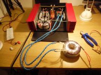
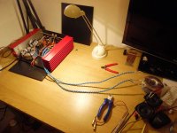
Anyway at last I made a change so now I can take out the trafo easily, I guess tomorrow I 'll check if it helps when I move it far away...
Any idea why this 2 x 10R increased my hum a little bit..?

I just want to mention that, make sure you didn't put Power Supply decouple capacitor to signal ground. Even if you did, the value should be no more than 0.1uf. Those capacitor will introduce power ripple to the signal ground. Because the ripple on + rail won't perfect mirror to the ripple on - rail. That's why when you put equal value capacitors on both rails to ground. They will drag the ground off ZERO point!
Last edited:
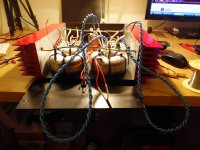
Report: I couldnt wait for testing this trafo EMF at last... 🙂
Moto: it is 100x times more useful to try something instead of asking/reading a lot... 🙂
Tests
Conclusions
Moto: it is 100x times more useful to try something instead of asking/reading a lot... 🙂
Tests
- just using 1 side of this dual mono layout
result: the hum didnt change at all - secondary polarity changes (all the 4 combination)
result: the hum didnt change at all - wiring the main AC line far from the whole amp from front direction
result: the hum didnt change at all
To further: the amp is 100%-ly insensitive to main AC line!
Even puting it directly to the pot, input, FB wire, etc... Nothing hum incresing at all... - inactivating the earth
result: in my case the hum decreased a bit (heatsinks & pot case still wired together and via 10R+10nF to amp GND) - using EXTRA long ~ 1m secondary wires
result: the change was subtle, even when laying them directly to the sensitive parts(!!!) - puting the trafo far away
result: nothing changed - experimenting to holding the trafo to all parts of the amp in any kind of position
(sorry, no pictures I have only 2 hands... 🙂)
result: the trafo already could cause bigger hum but only at the input part, the PS and the OPS are completely insensitive to it.
Other: in some angles even holding it 1cm from the pot it didnt made any additional hum...
And in opposite with ostripers experiences: I found that the radiation is LESS at the P/S takeoff points.
Conclusions
- There are a lot of misbeliefs and misunderstandings carried on without testing.
- In a distance like at my layout the trafo EMF doesnt count (when there is no other big problem with wiring, grounding, etc...)
- Sec polarity: related to hum I didnt experienced any difference.
- Pri polarity: this maters clearly (in my case ~3x times more hum).
- Sec EMF: when the loops are minimized/twisted the EMF is subtle.
- Trafo placement: puting it directly to sensitive input section can be hard without shielding (as expected).
Attachments
I disagree. In my case for example there is no GND at OPS at all...Any current fed out from OPS will find a way to flow back
To the speaker the physical current path is: PS rail -> OPS -> speaker "+" -> speaker -> speaker GND -> PS GND.
You cannot change on this. And I dont see why any additional noise would be added anyway.
It is completely independent from the pot position!Does the hum vary with different sources or does it stay the same? Does the hum respond to input volume or not?
On the signal GND there is only the signal input GND and the FB GND nothing else.I just want to mention that, make sure you didn't put Power Supply decouple capacitor to signal ground.
Now this point goes to main PS GND via a 10R resistor but it didnt helped in my case.
As it seems its not a channel crosstalk...?!
Last edited:
Yes, often the source of hum isn't even ground noise. It would be easy to shield those transformers with some screen door mesh, which seems to be what you need since primary phase determines whether primary or neutral noises are radiated statically from the outer windings.
EDIT: Or it could be that antiphase primaries are canceling the toroidal magnetic fields. See if a grounded piece of foil between trafos and amp reduces hum? If so then it's static interference.
EDIT: Or it could be that antiphase primaries are canceling the toroidal magnetic fields. See if a grounded piece of foil between trafos and amp reduces hum? If so then it's static interference.
Last edited:
And how this statically radiated noise works?
You mean it spreads in a capacitive way from pri to sec and then to the PS?
But even the it is not clear to me ho can a 50Hz/100Hz hum go through the big filter caps an on the FB..?!
You mean it spreads in a capacitive way from pri to sec and then to the PS?
But even the it is not clear to me ho can a 50Hz/100Hz hum go through the big filter caps an on the FB..?!
Static interference travels through the capacitance of the air. At 120V it is pretty significant, and gets worse as frequency increases, so higher frequency noise on the rails can couple surprisingly well into bare high-impedance traces, enough to cause hum. Think of it like a smelly pillow coming out of your toroid in all directions and pushing up against your circuits. You need a grounded shield to contain the pillow.
Last edited:
Can you show us your PSU PCB layout? Is your star ground 'T' d off from the PSU cap 0 V?
If moving the transformer does not change the hum, your problem may be more related to common impedance coupling see Daniel Joffe's first example.
If moving the transformer does not change the hum, your problem may be more related to common impedance coupling see Daniel Joffe's first example.
Re 'Bonsai's 15 Ohm Resistor'.
I seem to have drawn quite some flack on the location of the 15 Ohm resistor!
Ground loop currents have a number of paths thet can take. You want to steer them for the most part out to the mains plug earth pin as quickly as possible. The 15 ohm resistor is designed to facilitate that. I have mentioned a few times that further improvements can be had by bonding the RCA 0V where they come into the chassis to the IEC mains receptacle earth (the RCA's must still be isolated from the chassis!). What we are trying to do here with the 15 Ohm resistor is encourage any earth loop currents to exit the amp via this route rather than onto the amplifer PCB and then through the 0V power supply wire, to the star gound and then the chassis and finally out via the IEC receptacle. One of the reasons a ground lifter between the amplifer 0V and the chassis works so well in some case cases is because we are not providing a path for the ground loop through the amplifier 0V.
In all of these scenarios, you have to assume that both the source and the power amp are solidly earthed to the mains ground - safety comes first.
You will never stop induction induced noise in the interconnecting cable - Whitlock also alludes to this. You have to use decent interconnects, and keep them away from mains cables etc. But, in most cases, this is not the biggest source of noise in my experience - its the earth loops, bad wiring practice etc.
🙂
Cortez, have you tried re-routing your mains cable to the switch well away from the pot and small signal wiring? Even with a 10k pot, set to say mid position, it will take surprisingly little capacitive coupling to introduce hum and noise with the configuration you show,
Yes I agree if moving the trafo away didnt solve it it shouldnt be a radiated pollution...
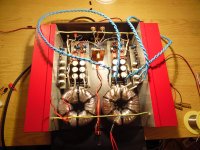
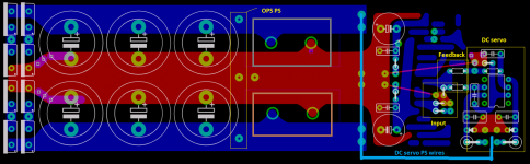
PS PCB:
Here you are! I tried to show only the relevant parts with colorization:
The red trace is the GND. You can see the rectifiers, the main filter caps,
(the last squared ones are 2.2uF oil paper caps for smoothing HF), the IPS PS.
As you can see the input section is very compact.
Now instead of that red wire going to the main GND trace there is the 10R resistor.
Any comments...?
In the meantime I am simulating the AC based PS with LT (untill now I just used +- DC sources...)
and I dont know why but it also shows some ripple voltage at the output even when shorting the input...
Attachments
Didnt you read #63?Cortez, have you tried re-routing your mains cable to the switch well away from the pot and small signal wiring? Even with a 10k pot, set to say mid position, it will take surprisingly little capacitive coupling to introduce hum and noise with the configuration you show,
I tested this as well, surprisingly it didnt made any difference.
To further taking it very very close to the ipnut/pot did not cause any increase in the hum at all!
Re 'Bonsai's 15 Ohm Resistor'.
Ground loop currents have a number of paths thet can take. You want to steer them for the most part out to the mains plug earth pin as quickly as possible. The 15 ohm resistor is designed to facilitate that. I have mentioned a few times that further improvements can be had by bonding the RCA 0V where they come into the chassis to the IEC mains receptacle earth (the RCA's must still be isolated from the chassis!). What we are trying to do here with the 15 Ohm resistor is encourage any earth loop currents to exit the amp via this route rather than onto the amplifer PCB and then through the 0V power supply wire, to the star gound and then the chassis and finally out via the IEC receptacle. One of the reasons a ground lifter between the amplifer 0V and the chassis works so well in some case cases is because we are not providing a path for the ground loop through the amplifier 0V.
🙂
But if you do that the signal return has a fairly tortuous path from RCA to the amplifier. You need a signal loop. Or did you mean earthed from RCA to IEC as well as a -ve to the amplifier?
Bill, ok - let me clarify
1. From the RCA to the amplifier PCB you run your screened cable in the normal way (screen plus signal). The 15 Ohm resistor is as I show on the amplifer PCB
2. From the RCA socket (which are still isolated from the chassis) ground connection, you run a bonding wire directly to the IEC earth
The ground loop now flows out to earth via the bond, and NOT through your amplifier PCB ground to the star ground.
I have tried the above technique and the ground lifter technique - both are very effective.
If you do not put the 15 Ohm resistor as I show, then you still run the risk that the earth loop flows through the amplifier PCB. If you still do not like the 15 Ohm resistor, then use a ground lifter between amplifier 0V and the chassis.
Last edited:
Yes I agree if moving the trafo away didnt solve it it shouldnt be a radiated pollution...
PS PCB:
Here you are! I tried to show only the relevant parts with colorization:
The red trace is the GND. You can see the rectifiers, the main filter caps,
(the last squared ones are 2.2uF oil paper caps for smoothing HF), the IPS PS.
As you can see the input section is very compact.
Now instead of that red wire going to the main GND trace there is the 10R resistor.
Any comments...?
In the meantime I am simulating the AC based PS with LT (untill now I just used +- DC sources...)
and I dont know why but it also shows some ripple voltage at the output even when shorting the input...
If I am reading your diagram correctly, the 0V goes to the amplifer PCB, and there you terminate your on board decoupling and your speaker return - so there is only one 0V wire between the PSU 0V and the amplifer PCB. Is that correct?
Last edited:
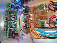
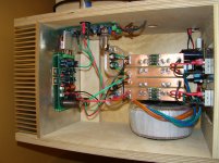
Here are a couple shots of amps I'm running. These are all the way quiet...as in ear to the cone and no noise. Since the photos I have installed the safety ground from the ground pin of the ac inlet directly to the heatsink and from there connected to the power supply ground through a cl60 thermistor. The amps were equally quiet with and without this addition. In retrospect I might do a few things differently but I probably wont mess with what works.
Evan
Evan
Attachments
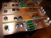
Wow - nice furniture Evan! I salute you! 🙂
It looks to me like you have kept the mains side of things completely separate from the signal part (2nd photo above, mains power on RHS and signal on Left).
For the ground lifter, the general idea is to connect the chassis (normally this is metal - but in your case of course its not) directly to the mains earth for safety reasons. The ground lifter then sits between the chassi and the amplifier 0V. Suggest in your case your just return it to the way you had it.
Last edited:
Yes! The speaker GND wire goes to that GND point in the middle of the OPS PS section.If I am reading your diagram correctly, the 0V goes to the amplifer PCB, and there you terminate your on board decoupling and your speaker return - so there is only one 0V wire between the PSU 0V and the amplifer PCB. Is that correct?
Is this correct? I tried to develop it correctly even 2-3 years ago when I made it... 🙂
After switching off or unplugging the amp it should play for a few seconds, does the hum stop? You have removed the ground loops already and proven that the hum doesn't originate from the transformer location. That leaves rail and/or ground noise or maybe the servo.
And how this statically radiated noise works?
You mean it spreads in a capacitive way from pri to sec and then to the PS?
But even the it is not clear to me ho can a 50Hz/100Hz hum go through the big filter caps an on the FB..?!
The caps "hum" , as well.
Even as they are smoothing a rectified trafo secondary , that 50/60hz
still comes through as charging pulses at the caps.
Hold a tiny amplified audio trafo near the main caps or rail lines and you will
hear that 50/60hz plus harmonics (quite a different sound than the pure AC/trafo) ... lower level - but it is still there.
When this rectified "hum" reaches the amp , it's feedback/PSRR cancels
this out -just a simple "unregulated supply" - not perfect.
For more intolerant amps (CFA's) ,I added cap multipliers as an offset for this weakness.
OS
- Status
- Not open for further replies.
- Home
- Amplifiers
- Solid State
- Ultimate Hum Terminator Thread