the speaker RETURN should follow the speaker FLOW route.
That FLOW route will be quite complicated in that it passes around and through various components INSIDE the Amplifier.
But the Flow route is not just from the Amplifier to the chassis mounted speaker terminal.
The current comes from the Main Smoothing capacitor/s in the PSU and from the supply rail decoupling capacitors in the Amplifier.
I have suggested a few times that one draws out the actual ROUTE on a plan of assembly.
That route should make it clear that the PSU supplies current to the amplifier and that same current then passes to the speaker terminal.
The RETURN ROUTE should follow the Flow Route all the way back to the Source.
That MUST take part of the Return Route past some of the amplifier components.
the speaker RETURN should follow the speaker FLOW route.
That FLOW route will be quite complicated in that it passes around and through various components INSIDE the Amplifier.
But the Flow route is not just from the Amplifier to the chassis mounted speaker terminal.
The current comes from the Main Smoothing capacitor/s in the PSU and from the supply rail decoupling capacitors in the Amplifier.
I have suggested a few times that one draws out the actual ROUTE on a plan of assembly.
That route should make it clear that the PSU supplies current to the amplifier and that same current then passes to the speaker terminal.
The RETURN ROUTE should follow the Flow Route all the way back to the Source.
That MUST take part of the Return Route past some of the amplifier components.
So should the speaker return wire be twisted in with the amplifier board rail feeds back to the supply, or connected to the amplifier board ground and returned through the ground? Or just routed along side the rail feeds?
post30,
Cortez, I think you have copied the sch from Bonzai.
The decoupling resistor is in the wrong location.
I tried to explain this to the Author. He asked for further information so that we could understand the alleged "problem".
I sent a long explanation via the Forum as requested.
The Author did not reply !
I have downloaded the current pdf "how to wire up a power amplifier - updated"
the decoupling resistor is still in the wrong location.
Andrew, for the schematic I show in my diagram, the resistor is in the correct position. As I explained, in some cases you may need the bond from the input RCA ground to the IEC receptacle.
The test of any wiring scheme is:-
1. Zero hum with no inputs connected (and I mean zero)
2. Zero or very low hum with input source connected. Very low hum means a few hundred uV. You have to have your ear inside the speaker cone to detect anything (checked by a 20 year old with good hearing!)
These are the criteria I set myself.
I have Daniel Joffe's article - its very good and explains the mechanisms succinctly. In my PDF I've shown how to wire it up practically. I will add a non ground lifter version in the next few weeks. I would also add that the overall layout, cable dressing etc are all important points to adress in getting zero noise.
Last edited:
The test of any wiring scheme is:-
1. Zero hum with no inputs connected (and I mean zero)
2. Zero or very low hum with input source connected. Very low hum means a few hundred uV. You have to have your ear inside the speaker cone to detect anything (checked by a 20 year old with good hearing!)
Now most say you should have zero hum with 1k strapped across the inputs. Certainly makes testing easier if the test case is with floating inputs.
So should the speaker return wire be twisted in with the amplifier board rail feeds back to the supply, or connected to the amplifier board ground and returned through the ground? Or just routed along side the rail feeds?
The speaker return should not in my view go back to the amplifer PCB ground. You have large currents - and at HF - flowing in the speaker return. This places a noise voltage source (IR or ~IL at HF) in series with the amplifier PCB ground and can lead to problems. To minimize the radiating area, just route the cable back to the star ground (or 'T' which is what I use) but follow the speaker drive (i.e. the +ve speaker wire). There will be a short part where the two are not in close proximity, but it will in general not be a problem.
For the power cables, I bunch the +, - and 0V closely together to reduce radiating area.
Now most say you should have zero hum with 1k strapped across the inputs. Certainly makes testing easier if the test case is with floating inputs.
I use 10k input bias resistors on my amps - this is what I test with. I dont think 1k would make all that much difference in this context though.
Wow! Another great article in this topic!Read D.Joffe article.
Thank U very much I link it in the 1st post immediately...!
And then I'll try this 10R soon...
I thought it is only for breaking external ground loop when earthing is improper but as I see
it is essential in every case to prevent any unwanted current between the 2 channel PGND.
The speaker return should not in my view go back to the amplifer PCB ground. You have large currents - and at HF - flowing in the speaker return. This places a noise voltage source (IR or ~IL at HF) in series with the amplifier PCB ground and can lead to problems. To minimize the radiating area, just route the cable back to the star ground (or 'T' which is what I use) but follow the speaker drive (i.e. the +ve speaker wire). There will be a short part where the two are not in close proximity, but it will in general not be a problem.
For the power cables, I bunch the +, - and 0V closely together to reduce radiating area.
Thanks.
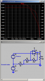
This works much better than the resistor in post 30, which will apply ground noise to the amplifier's full gain:
http://www.diyaudio.com/forums/construction-tips/251996-ground-loops.html#post3845378
And a good app note by Bruno Putzeys:
http://www.hypex.nl/docs/appnotes/pin1_appnote.pdf
http://www.diyaudio.com/forums/construction-tips/251996-ground-loops.html#post3845378
And a good app note by Bruno Putzeys:
http://www.hypex.nl/docs/appnotes/pin1_appnote.pdf
This works much better than the resistor in post 30, which will apply ground noise to the amplifier's full gain:
http://www.diyaudio.com/forums/construction-tips/251996-ground-loops.html#post3845378
And a good app note by Bruno Putzeys:
http://www.hypex.nl/docs/appnotes/pin1_appnote.pdf
I'd like to try this in my amplifier. Is the choke best placed at the signal input to the chassis or right at the input connection to the amplifier board itself?
Either will do as long as it's inside the chassis. I would put it at the PCB, because the wire from the PCB to the choke is more susceptible to static interference, so decreasing it's surface area is a good thing. This is not very important though if your transformer is shielded (easily done with some conductive screen door mesh).
It depends on where the Main Audio Ground (MAG) is.So should the speaker return wire be twisted in with the amplifier board rail feeds back to the supply, or connected to the amplifier board ground and returned through the ground? Or just routed along side the rail feeds?
In a Mono block the MAG can be on board. That becomes the tapping point for the speaker return after it has followed the Flow route. i.e. spk ret terminates on the PCB.
In a multi-channel amplifier the MAG is generally off board. The spk ret passes across the amplifier and follows the power wiring till they reach the MAG. There the Power wiring is attached to the MAG and so too would the spk ret.
In both the above the final return route is along the PSU zero volts wire that is bundled inside the power triplet. Inside the bundle achieves the lowest Loop Area for that final route to the source (PSU caps).
Does anyone have any experience with these? I had a friend give me one since he's closing shop, and if I can drop the little bit of hum I have by using it in front of some more sensitive gear, is there any danger in trying it? I don't want to cause a problem using it with 1 or two pieces of gear that's connected to other gear that isn't.
Attachments
We had this disagreement some weeks ago and you asked me to explain on the Forum so that we could air our "beliefs" in public. I did that but you did not reply. The discussion ended up one-sided with no resolution.Andrew, for the schematic I show in my diagram, the resistor is in the correct position. As I explained, in some cases you may need the bond from the input RCA ground to the IEC receptacle.
The test of any wiring scheme is:-
1. Zero hum with no inputs connected (and I mean zero)
2. Zero or very low hum with input source connected. Very low hum means a few hundred uV. You have to have your ear inside the speaker cone to detect anything (checked by a 20 year old with good hearing!)
These are the criteria I set myself.
I have Daniel Joffe's article - its very good and explains the mechanisms succinctly. In my PDF I've shown how to wire it up practically. I will add a non ground lifter version in the next few weeks. I would also add that the overall layout, cable dressing etc are all important points to adress in getting zero noise.
Yes the added resistance is needed where there is a loop and that loop carries interference current that impinges on the wanted signal. BUT the resistance has to be located where it does NOT add interference voltage in the signal route.Wow! Another great article in this topic!
Thank U very much I link it in the 1st post immediately...!
And then I'll try this 10R soon...
I thought it is only for breaking external ground loop when earthing is improper but as I see
it is essential in every case to prevent any unwanted current between the 2 channel PGND.
Note carefully where HBRR is located. Bonzai has the resistor on the wrong side of the adjacent junction. He has located the resistor IN the signal route.
Bonzai's location does reduce the current, but the resistance adds the interference voltage to the signal voltage. I think you had spotted this when you said:
"If any ground current flows via this 15R then it will be added to the clean input signal, wont it..? (attachment)"
Yes to your question "won't it..?"
The Joffe attenuation works because the added resistor reduces interference current AND moves the predominant interference voltage (interference current times added resistance) into a part of the Loop that is outside the Signal Flow and Return Route.
Last edited:
The 15R resistor in Bonsai's PDF is a terrible solution. As you can see, the noise is amplified by the full gain.
Connecting the feedback ground on the other side of the resistor is better, but the ground noise is still added at a gain of 1.
Reducing the ground path length will reduce the voltage developed, but that won't help when most of the resistance causing the problem is the input cable's shield. Furthermore, since ground loop currents have no return path inside the chassis, it will radiate magnetically with no way of twisting with the return path to cancel the field.
So the ultimate solution is to break the ground connection without adding ground noise directly to the signal. This is why I suggested my CMC ground isolator, which does exactly that. This is a common EMC technique.
On that note, if you really want some empirical knowledge of interference and different situations, as well as advanced, highly useful articles on different EMC problems and solutions, you can register here for free:
EMC Information Centre
Attachments
Last edited:
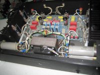
Well here is my practical input to all this. Exhibit A, one counterpoint SA100 that has hummed since I got it. Previously my room was big enough that I could ignore it so I did, thinking that it would encourage me to get back into DIY. Well I finally have, but finances have stalled the new amp build, so I need to eke another 6 months out this beast. Should be useful for testing the theories on this thread because it is a sub-optimal design at best. I am going to pretend to be thick and follow instructions as given to see if they work, as this should prove things.
First thing to note is that yes, the input mains cable runs all the way under the main board to the transformer at the front of the chassis! So unless anyone can suggest otherwise steps 1 and 2 are dealing with that and the input wiring. The main board is loosely dual mono with left and right diode bridges and smoothing caps. The speaker return runs under the main board.
Photo btw is not of mine, but broadly similar. Welcome any additional suggestions except for 'ugh rip it out and put a proper amp in the case' as I am sorely tempted, but would like it to be some use before then.
Attachments
Report: I just added the 10R I hope to the right place... 🙂
(Between the SGND and PGND so the signal input GND and the FB GND are at the same point.)
Result: did not resolve my remaining hum... 🙁
I dont say it didn't changed anything: its a bit worse...
I really dont get it now the hum sounds like a real ground loop hum (~ clear 50Hz) and is a bit louder then before.
But my problem is still inside so the inputs are shorted during testing without any source connected.
Anyway at last I made a change so now I can take out the trafo easily, I guess tomorrow I 'll check if it helps when I move it far away...
Any idea why this 2 x 10R increased my hum a little bit..?
Last edited:
No, the speaker's ground IS at the main PS GND anyway.
Sometimes designers put this point to the OPS PCB but that's just using more (unnecessary) cable.
PS caps @ OPS are for the supply rails (decoupling the long wires inductance and resistance) and it isn't related directly with the load (speaker).
Any current fed out from OPS will find a way to flow back, even if you deliberately connect speaker ground away from OPS. The current will find its way back to OPS (Maybe through +- power rails or signal ground!). Connecting speaker return to main PS ground will make the noise issue worse. It will make local ground noise issue become system-wide ground / power supply noise issue.
By the way, there should be a signal ground separated from power ground, so that speaker return will not mess up signal reference point.
Last edited:
- Status
- Not open for further replies.
- Home
- Amplifiers
- Solid State
- Ultimate Hum Terminator Thread