RK27 (pot): yes, the holder is a 2 sided PCB with a clean copper surface and te pot nut holds it tightly to it.
Belly band: I just ordered 2 trafos a few days ago but furtunately I still could modify my order and ask for these extras:
core lead out, shielding between P/S, belly band so we'll see the difference... 😉
jneutron: ok thx for the tip, I invite him!
New experience: when I put my hand to the left heatsink and as I touch the trafo as well at the same time, the hum changes!
Are the heatsinks taking up/conducting maybe the stray magnetic field to the OPS fixed on them?!
The HSs may be too near to the trafos..?!
What would happen if you turned the trafos 90 degrees to the present orientation or turned just one of them so the fields don't line up the way they do, do the two fields in a non shielded trafo add together or are they bucking each other?
Just two inputs to add to our subjects of reflexion.
The first one is about AC trasfos and their leakages.
The toroids are good for magnetic leakages, but present a pretty bad capacitive isolation between primary and secondary coils. And most of them don't offer a screen between primary and secondary. I wonder why manufactures don't off C trasfos, witch are the best about this problem.
Too, the sens of the AC pug have an importance, when you connect together two (or more) AC powered devices. Using your analog preamp as the starting point, not connecting the earth in the main AC plug, i use to measure the voltage between the plug earth and the preamp chassis, and find the AC sens where this voltage is minimal.
From there, not connecting the signal between the power amp and the preamp, neither the earth of the power amp, i use to measure the voltages between the two chassis and chose the AC sens of the power amp where there is the less Voltage. Continuing that way with all the devices you connect to the preamp, one after the other.
The second thing is the importance to find the best point in the chassis where you will connect the earth to it. And the efficiency of various way to provide in the same time enough isolation between ground and earth, while maintaining safety (Diodes, as an example).
Waiting for your comments.
Last edited:
Should the speaker ground connect to somewhere near Out Put Stage? If it connects to Power Supply Ground, what's the meaning for PS decouple of Out Put Stage?
I dont want to move them now but anyway a I saw a lot of other amp with aWhat would happen if you turned the trafos 90 degrees to the present orientation or turned just one of them so the fields don't line up the way they do, do the two fields in a non shielded trafo add together or are they bucking each other?
similar trafo positioning so I guess this should work without any hum hopefully... 🙂
No, the speaker's ground IS at the main PS GND anyway.Should the speaker ground connect to somewhere near Out Put Stage? If it connects to Power Supply Ground, what's the meaning for PS decouple of Out Put Stage?
Sometimes designers put this point to the OPS PCB but that's just using more (unnecessary) cable.
PS caps @ OPS are for the supply rails (decoupling the long wires inductance and resistance) and it isn't related directly with the load (speaker).
Strange discovery: the noise increases when I try the AC plug with the opposite "polarity" to the outlet... 😛
Bonsai, I saw on your website that you have a newer version of your PDF:
http://hifisonix.com/wordpress/wp-c.../How-to-wire-up-a-Power-Amplifier_Updated.pdf
(I'll update the first post pointing to this as well...)
I think its very complete now I am not sure we need a new one...
Bonsai, I saw on your website that you have a newer version of your PDF:
http://hifisonix.com/wordpress/wp-c.../How-to-wire-up-a-Power-Amplifier_Updated.pdf
(I'll update the first post pointing to this as well...)
I think its very complete now I am not sure we need a new one...
You were lucky at the game of heads or tails ;-)Strange discovery: the noise increases when I try the AC plug with the opposite "polarity" to the outlet... 😛
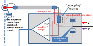
Cortez, the original version had the 15 ohm isolation resistors in the wrong position. The updated version has them drawn correctly
Cortez, I think you should look at these aspects in your amp:
1. You run the mains supply under the pot. The mains is carrying the cap charging currents which are full of harmonics and will easily couple to the input
2. Your mains entry and cabling to the trafos needs to be very short and preferably all close together. On your second picture, I'd put the mains input socket at the top of the picture with the mains switch close by. On some of my amps I put the switch on the back panel for just such a reason.
3. You have to keep the power wiring well away from any input wiring, and especially AC and raw rectified DC. Twisting wires makes a huge difference but will not mitigate hum and noise if the input and power cables are in close proximity.
4. Remember that the main filter caps are also very noisy because they are sucking up the charging current spikes at 2 x Fmains - for EU that's 100 Hz and USA 120 Hz. On a typical power amp, the charging current peak can be at 20 or 30 Amps, and on a big amp 3 or 4 times as high. So, keep signal wiring and small signal circuitry well away from the power supply capacitor banks.
Hmm.. Are you sure..? I checked and the 15R is now in series with the input signal.Cortez, the original version had the 15 ohm isolation resistors in the wrong position. The updated version has them drawn correctly
If any ground current flows via this 15R then it will be added to the clean input signal, wont it..? (attachment)
Main supply advices: I decided to try out taking out (and far) my
trafo even if I have to disassemble my almost finished amp... 🙂
I'll try to rotate the trafo and to put it 1m away just to check that
the hum is due to stray magnetic field or improper ground wiring...
In these test I'll run the main AC line far from the pot and the whole
input part as well though I checked this with the external AC cable and
to moving it close to any part of the amp didnt change the hum at all...
About the main filter caps: I read somewhere that dispite of the high
charging currents they do not radiate a huge field around them because
of their internal structure and small surface loop of conducting material.
ostriper, do you have memories about main filter caps stray field based
on your experiment with that small audio transformer-sensor?
Nonetheless as you can see the layout is "linear" and the order is (from high current sections to sensitive parts):
- trafo
- rectifier
- main filter caps || OPS
- IPS PS
- IPS
- Pot & input RCA
Attachments
Last edited:
Cortez,
I'm no expert on anything electronic, my specialty is on the speaker side of things but a few things I am thinking. On the radiated energy from the supply caps what I think Bonsai is saying is that the radiation from the charging of these caps gets superimposed onto the power rails and lead wires supplying the amp, not from the caps themselves radiating that energy. I was thinking that another solution for the magnetic field from the trafo could be minimized by covering it with Mu metal. I don't know if you connect the Mu metal to the star ground, someone else will have to answer that. I don't expect very many people are up here in the States as it is 1:20 AM on the West Coast right now. Of course I am up working on a cad design that I have to present tomorrow, the life of a designer!
Perhaps one day I will get to come to your country and see where my grandparents came from. It is hard to tell what was Hungary and what was Austria and things like that as the borders changed so many times over the years. The history on my mothers side has basically been lost after WWII so I don't know much about what came before, it would be interesting to see all the places my ancestors came from. I know on my fathers side they were Dutch and German and now what is called Ukraine as my grandfather was born in Odessa. He always said his family was of Russian decent but who really knows? He left there in 1903 when he was only 3 years old when he came to America. I am not religious and haven't been raised with any real religious training but many of my ancestors were Jewish so it is almost impossible to know what came before. I also have Lutheran on my grandmothers side so I just consider myself a mutt!
Your equipment should all be well earthed so the loop currents will flow in the earth wires. Connect a wire from the input RCA to the 3 pin IEC earth and check as this can also provide very good hum reduction. What you are doing here is offering the loop current a very nice easy path straight out of your amp chassis to earth, while the 15 ohm resistor ensures it does not prefer to flow to your star ground through the PCB and wires to the PSU. The addition of a ground lifter also helps here as I show in the diagram.
Re caps radiating hum. They do - just try routing your input wire over and around the caps - it's noisy. Of course it's much lower than say a trafo, but it's still unacceptable and especially so if you put 25-35 DB of gain after that.
Re caps radiating hum. They do - just try routing your input wire over and around the caps - it's noisy. Of course it's much lower than say a trafo, but it's still unacceptable and especially so if you put 25-35 DB of gain after that.
Last edited:
Bonsai,
So the caps themselves are that noisy. I wouldn't have expected that as I have always seen the main supply caps placed so close to the rest of the circuitry with no attempts to shield them. Could a Mu metal can be placed around the trafos to block some of the radiated energy or does that not work?
So the caps themselves are that noisy. I wouldn't have expected that as I have always seen the main supply caps placed so close to the rest of the circuitry with no attempts to shield them. Could a Mu metal can be placed around the trafos to block some of the radiated energy or does that not work?
Kindhorman, its the charging currents into the caps that causes the problem. They are not as noisy as trafo. But, you cannot route small signal cables or circuitry around the main filter caps.
post30,
Cortez, I think you have copied the sch from Bonzai.
The decoupling resistor is in the wrong location.
I tried to explain this to the Author. He asked for further information so that we could understand the alleged "problem".
I sent a long explanation via the Forum as requested.
The Author did not reply !
I have downloaded the current pdf "how to wire up a power amplifier - updated"
the decoupling resistor is still in the wrong location.
Last edited:
I checked it using the input cable with a loop as a EMF sensor but @ the caps there was nothing noise at all.
It is really interesting to "see" (hear) these trafo EMF "lines" in the space with a test like that.
I dont know why but it was the strongest in the corners at the heatsinks!
And of course in the middle between the 2 trafos and all around the edges.
(Also at the sec takoffs I didnt hear anything extra...)
By the way in the morning I did some other mods (not for hum elimination at all) and now the hum is
quite acceptable so I save my self to disasseble the whole PS part for now... 🙂
The mods were:
The hum is not "0" but I hardly cant hear it from 10-15cm.
I also can imagine that my AC main line is playing with me from time to time
for example having less noise or DC component or something like that... 🙂
And from the 2 chanel the one which is sensitive to the AC plug polarity is a bit louder,
so I guess this should be some trafo level garbage and not a wiring/grounding issue any more...
It is really interesting to "see" (hear) these trafo EMF "lines" in the space with a test like that.
I dont know why but it was the strongest in the corners at the heatsinks!
And of course in the middle between the 2 trafos and all around the edges.
(Also at the sec takoffs I didnt hear anything extra...)
By the way in the morning I did some other mods (not for hum elimination at all) and now the hum is
quite acceptable so I save my self to disasseble the whole PS part for now... 🙂
The mods were:
- removing some unnecessary washers (metal) @ power transistor screws
(I dont know wheter these helped reduce hum at all...) - make the IPS -> OPS twisted pair a bit shorter
- adjusting the trimmer of a HF compensation RC element @LTP
- as an experiment: leading the FB from the speaker conenction to the IPS (instead taking it from the OPS)
(I didnt see any difference in behaviour at all...)
The hum is not "0" but I hardly cant hear it from 10-15cm.
I also can imagine that my AC main line is playing with me from time to time
for example having less noise or DC component or something like that... 🙂
And from the 2 chanel the one which is sensitive to the AC plug polarity is a bit louder,
so I guess this should be some trafo level garbage and not a wiring/grounding issue any more...
Read D.Joffe article.
It explains what the problem is and how to attenuate it.
http://www.diyaudio.com/forums/soli...ichael-bittner-our-mikeb-198.html#post4024136
post3941 in case the link misdirects you.
Bonzai also linked to the same article
http://www.diyaudio.com/forums/analog-line-level/265232-comment-grounding-scheme-11.html#post4170245
Last edited:
Read D.Joffe article.
It explains what the problem is and how to attenuate it.
http://www.diyaudio.com/forums/soli...ichael-bittner-our-mikeb-198.html#post4024136
post3941 in case the link misdirects you.
Is this the article you are referring too? http://www.updatemydynaco.com/documents/GroundingProblemsRev1p4.pdf
yes,Is this the article you are referring too? http://www.updatemydynaco.com/documents/GroundingProblemsRev1p4.pdf
fig5 shows the added resistor: HBRL and HBRR, one in each channel.
They reduce the interference current when the two interconnects come from a Source component that has a common Signal Return.
There seems to be a lot of disagreement as to the proper routing of speaker returns. Some say route them straight to the star ground. Others say route them back to the amplifier ground connection.
My understanding of the operation of the twisted pair/triplet cable is the emissions from the feed currents and the emissions from the return currents should cancel each other out in the twisted pair/triplet. The current return is flowing through the speaker return, not the amplifier ground. Is that not needed to be included in the twisted pair/triplet for it to function properly? Or do the + and - rails take care of the cancellation due to the amplifier being in class A ( assuming it's a class A or AB amplifier)?
My understanding of the operation of the twisted pair/triplet cable is the emissions from the feed currents and the emissions from the return currents should cancel each other out in the twisted pair/triplet. The current return is flowing through the speaker return, not the amplifier ground. Is that not needed to be included in the twisted pair/triplet for it to function properly? Or do the + and - rails take care of the cancellation due to the amplifier being in class A ( assuming it's a class A or AB amplifier)?
- Status
- Not open for further replies.
- Home
- Amplifiers
- Solid State
- Ultimate Hum Terminator Thread