That is an unusual way of getting hold of the chassis pico.Do you still have to get it to Oz or are you moving over there?
Moving there.
Thought it was kind of pointless shipping it to Australia then moving it to the USA.
Oh wow, better get married soon indeed! 😀
Some more pictures.
Beautiful
Well one of my chassis has made progress:
International arrival - awaiting clearance
MELBOURNE VIC. Wed 10 Feb • 9:17am
The other one is still in Milan it seems.
International arrival - awaiting clearance
MELBOURNE VIC. Wed 10 Feb • 9:17am
The other one is still in Milan it seems.
Can't wait to see the totally awesome projects you guys come up with.
I will start getting myself organised to do some pcbs to make full use of the heatsink
I will start getting myself organised to do some pcbs to make full use of the heatsink
Looks like the twins got separated. One should be here today 😀 The other has been sitting in Frankfurt taking on the local scenery, along with a beer or two I'm sure, for a few days.
Both of mine have been in Frankfrut for the last couple days, even though Fedex is
still showing 'delivery by 8pm today'. 🙂
still showing 'delivery by 8pm today'. 🙂

I think there has been some delay in their Frankfurt hub since we had a couple more european shipments delayed due to "something happening beyond their control" (at least that is what they say)
Not a worry, Gianluca. This just makes two presents. I can only work on one at a time.
The first project to move (and be updated) for the new chassis will be eerily similar to Ozorfis 🙂 I may have to do the SE (BA-1) output boards first just so I don't look like a copy-cat. 😀
So much fun, so little time.
Thanks again for making this all possible Pico. OH!, and congratulations on your upcoming marriage and move. You've already found your queen, but Welcome to America! Sadly, Sexual Chocolate broke up, so your musical choices are limited. We'll have to see if they get back together for the March reboot.
I was copying your capacitor choice first 😀 Although accidently bying the much too big 630 Volts version 
What I found so far:
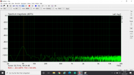
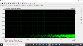
- As there is little space between mains connector and the input on the gainstage, I put a iron shield of 50x80x3 mm inbetween, which gave me -6db hum. Noise is now 0,18 and 0,35 mV, which I cannot hear anymore.
- 100 mA Bias on the gainstage extends the distortion free range (I guess class A range, because current stays constant until that point) to 2 Volts. But my sinks are 75°C already. I will get bigger ones and bias even higher. Would be awesome to mount them on the rear plate, if that was possible.
- I already have the 50mm long heat sinks on the rectifier pcb from the shop and they run 80°C
- silicone isolated solid core wires get easily cut when wiring beneath (will round the edges next time)
One day I also might try the single ended version as I still have 70 matched mosfets
Good luck everybody with their builds
What I found so far:
- As there is little space between mains connector and the input on the gainstage, I put a iron shield of 50x80x3 mm inbetween, which gave me -6db hum. Noise is now 0,18 and 0,35 mV, which I cannot hear anymore.
- 100 mA Bias on the gainstage extends the distortion free range (I guess class A range, because current stays constant until that point) to 2 Volts. But my sinks are 75°C already. I will get bigger ones and bias even higher. Would be awesome to mount them on the rear plate, if that was possible.
- I already have the 50mm long heat sinks on the rectifier pcb from the shop and they run 80°C
- silicone isolated solid core wires get easily cut when wiring beneath (will round the edges next time)
One day I also might try the single ended version as I still have 70 matched mosfets
Good luck everybody with their builds
Attachments
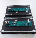
Maybe I will try to mount the gainstage mosfets beneath the pcb with a bit higher standoffs.....although disassembly would mean desoldering 
Ozorfis - I am still debating whether to mount them linearly (like you have) or with the PCBs at a 90 degree angle from the heatsinks. Once I get the chassis in-hand, it will make it easier to decide. 90 degree makes it easier to mount in other chassis, if I ever do that. Itsmee gave me the layout for that. If I do it linear like you, it makes the spread over the entire heatsink better.
Once I get things laid out, I'll share any ideas I come up with.
Once I get things laid out, I'll share any ideas I come up with.
My first chassis was delivered here today, all OK and accounted for. The second one is in Sydney this morning.
It appears that the EMS tracking data is not updated on a daily or as scanned basis. Yesterday my second package was still showing in Milan at the 5th Feb, then today the tracking shows 6 more entries from then till the 11th with it clearing customs in Sydney.
It appears that the EMS tracking data is not updated on a daily or as scanned basis. Yesterday my second package was still showing in Milan at the 5th Feb, then today the tracking shows 6 more entries from then till the 11th with it clearing customs in Sydney.

Yes pico, now plenty to do. By the way, I will send you the money for the caps tomorrow via Paypal.
Gianluca and the guys there did a great job - perfectly packed and no problem at all now unpacked.
Gianluca and the guys there did a great job - perfectly packed and no problem at all now unpacked.
Last edited:
Started to attach an F6 board to the heatsink pair. I thought one of the goals of the project was to drill the sinks so that the outputs transistors would line up symmetrically on each side of the centerline. Unless I'm just too tired the only way I can see to do that is to leave out one pair of attachment screws that line up over the split. If I goofed up, you can slap me on the head at the next BAF.
HeyBill,
Don't think that leaving out that particular pair of attachment screws for the PCB will be an issue if you use the other 6 holes of the PCB to firmly attach the PCB to stand-offs. You will have further support from the MOSFETs too, once they are soldered to the PCB and also fixed to the heatsink.
Probably you already are doing this, but doesn't hurt to mention - it's better if the the MOSFETs are mounted towards the bottom of the sink vertically, as the hot air will rise upwards through the fins. The OCD inside of us might suggest us to mount them in the vertical center too. 😉
6L6 shows it beautifully here - link below and image attached from his F6 illustrated build guide thread:
F6 Illustrated Build Guide
Attachments
Last edited:
- Home
- Amplifiers
- Pass Labs
- Ultimate 4U 500mm Chassis - Who is interested?