Hi aterren,
You also need to consider the max current rating of the RN112 choke (2A for the 1.8mH vs only 0.5A for the 18mH) and I didn't want to make tradeoff on this parameter.
Given I am using a full wave rectifier, the ripple frequency is 120Hz in your case so if I agree a lower cutoff would provide even better ripple characteristics, the present filter seems pretty OK to me if I trust my spice simulations results (using the 1.8mH choke).
In red, the AC voltage provided by the transfo, in green the voltage after the rectifier bridge, in blue the digital DC output.
Attachments

Some updates.
I am implementing now the dual encoder control.
I added on the existing right encoder the double pressed state and it works fine.
The additional left encoder channels can be added on the MCU spare I/F so we are good here.
The additional left encoder switch will be probably connected on one of the SW1-6 (front panel connector of the MCU board).
Then the changes vs. the switch:
- Switch 1-4 will be removed so changing the source (short press) will be done by rotating the left encoder and balanced / unbalanced mode on the fly (long press) will disappear and will have to be set in the setup menu for each input. Then starting on saved configuration 1-4 will disappear as well
- Switch 5 will be removed and will be replaced 1 to 1 by the left encoder (short press & long press)
- Switch 6 will be removed and will be replaced (short press) by the left encoder (double press)
- Switch 6 will be removed and will be replaced (long press) by the right encoder (double press)
It more or less make sense (this is the way I did on my DAC) except maybe for the switch 6 behavior (which is toggling between output 1 <and> 2 on a short press and setting output dual on a long press. Here I could also adjust a bit the code to only toggle between output 1 > output 2 > dual >output 1 ... with short press and remove the long press decoding and by consequence the dual press on right encoder)
For those who want this dual encoder, I let you tell me how you see things (remapping SW1-6 to the dual encoders) as I am close to complete the job then I will stop modifying the FW (except if bug) and release it.
Thanks for your comments, if no comments I will do as described above.
Ok thanks for your comment.
So 2 encoders and 1 switch.
What do you expect to see using this switch then?
So 2 encoders and 1 switch.
What do you expect to see using this switch then?
We managed to confuse each other a little bit Alex. I didn’t mean to keep a switch but instead have the toggle out1, out2, out1&2. On the left or right encoder (right could be long press for power off and short press to allow the right encoder to pick the output). Or output selection could be a power on menu for example with power off hold left encoder in and press right encoder enters a menu that allows you to select output 1 or 2 or both) and with no switch or encoder action for a short time the unit turns on with this setting stored.
As long as I can use the remote for sw5 and sw6 I don’t really care for all the double long / short options
As long as I can use the remote for sw5 and sw6 I don’t really care for all the double long / short options
Last edited:
You are really welcome. I will try to help always when I can.
Yes it is the slim line, good point let me add the link to HCFR.
I will add as well a link to a doc to debug the modules but in French, will need a translation later on...
depth is 350 ?
alu top / btm is good as the steel one ? (any issue with the internal clearances ?)
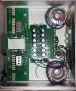
on top of that, can someone share some picture of the details for the trigger two-board assembly ? i don't quite get how it is supposed to link together... maybe with some wire bridge ?
thanks
We managed to confuse each other a little bit Alex. I didn’t mean to keep a switch but instead have the toggle out1, out2, out1&2. On the left or right encoder (right could be long press for power off and short press to allow the right encoder to pick the output). Or output selection could be a power on menu for example with power off hold left encoder in and press right encoder enters a menu that allows you to select output 1 or 2 or both) and with no switch or encoder action for a short time the unit turns on with this setting stored.
As long as I can use the remote for sw5 and sw6 I don’t really care for all the double long / short options
Hi Stones,
Ok clear now for the clarification on sw6.
Then as I mentioned I am not going to be able to make large changes (like adding a new menu) so I am just going to remap current sw1-6 short / long to 2 encoders.
BTW the remote is not controlling sw5 today and partially sw6 so what you propose at the end of your message is not possible.
depth is 350 ?
alu top / btm is good as the steel one ? (any issue with the internal clearances ?)
on top of that, can someone share some picture of the details for the trigger two-board assembly ? i don't quite get how it is supposed to link together... maybe with some wire bridge ?
thanks
Mine is shorter, 350mm is not needed.
I think some people did it in 170mm but personally I don't like as it look too short from an esthetically point of view especially when stacked with other audio equipments.
In the end it is really a matter of what you put inside.
Mine is steel but I know some used the aluminum without issues.
And right for the trigger boards it is just a resistor leg that you need to put in all wires that faces each other after chosing the right vertical PCB position in your chassis
Some updates.
I am implementing now the dual encoder control.
I added on the existing right encoder the double pressed state and it works fine.
The additional left encoder channels can be added on the MCU spare I/F so we are good here.
The additional left encoder switch will be probably connected on one of the SW1-6 (front panel connector of the MCU board).
Then the changes vs. the switch:
- Switch 1-4 will be removed so changing the source (short press) will be done by rotating the left encoder and balanced / unbalanced mode on the fly (long press) will disappear and will have to be set in the setup menu for each input. Then starting on saved configuration 1-4 will disappear as well
- Switch 5 will be removed and will be replaced 1 to 1 by the left encoder (short press & long press)
- Switch 6 will be removed and will be replaced (short press) by the left encoder (double press)
- Switch 6 will be removed and will be replaced (long press) by the right encoder (double press)
It more or less make sense (this is the way I did on my DAC) except maybe for the switch 6 behavior (which is toggling between output 1 <and> 2 on a short press and setting output dual on a long press. Here I could also adjust a bit the code to only toggle between output 1 > output 2 > dual >output 1 ... with short press and remove the long press decoding and by consequence the dual press on right encoder)
For those who want this dual encoder, I let you tell me how you see things (remapping SW1-6 to the dual encoders) as I am close to complete the job then I will stop modifying the FW (except if bug) and release it.
Thanks for your comments, if no comments I will do as described above.
for me it would be OK
Mine is shorter, 350mm is not needed.
I think some people did it in 170mm but personally I don't like as it look too short from an esthetically point of view especially when stacked with other audio equipments.
In the end it is really a matter of what you put inside.
Mine is steel but I know some used the aluminum without issues.
And right for the trigger boards it is just a resistor leg that you need to put in all holes that faces each other after chosing the right vertical PCB position in your chassis
Typo above.
I hope somebody can help me wrapping my head around a doubt regarding this preamp in dual module configuration (gain + buffer).
What is the rationale behind the fact that the first module is a gain stage ?
I mean, right after the input, we have the gain stage that goes "full-swing" and then it goes to the muse chip to be attenuated, and then, at the end, to the output buffer.
for example, my dac outputs a little over 4vpp, the gain module almost clip the signal, then it goes to the muse (at the limit of the input voltage range) and then to the buffer.
In order to have better thd at the output and (maybe) lower dissipation in the muse chip is not more "logic" (pass me the term...) to have the muse attenuator as the first stage, and then, feed the rest of the chain ?
I am pretty sure i am missing a BIG point in that, but please, enlighten me.
Ah... another thing :
when i set the volume at 0db, the output is supposed to match the input amplitude ?
My UGS module (built long before this preamp...) gives me (at 0db on the muse) 0.7x of the input signal (single module configuration... no buffer), maybe i need to re-adjust the feedback network. but, not sure
thanks 🙂
Last edited:
Hi gionag 🙂
I think like you do : Why increase the gain in front of the Muses ? Most of the sources have an output of 2v p/p (or more), like CD-players, Dac's and so on.
I use my pre. with the gain stage AFTER the Muse's, and no buffer.
I'm sure you will gett better thd. readings in this way.
But let's see Alex comment on this one 🙂
Regards
Johnny
I don't think you are missing a BIG point !I am pretty sure i am missing a BIG point in that, but please, enlighten me.
I think like you do : Why increase the gain in front of the Muses ? Most of the sources have an output of 2v p/p (or more), like CD-players, Dac's and so on.
I use my pre. with the gain stage AFTER the Muse's, and no buffer.
I'm sure you will gett better thd. readings in this way.
But let's see Alex comment on this one 🙂
Regards
Johnny
ok... so i am not entirely crazy 😱 (or we both are 🙂 )
btw, have you ever measured the attenuation/gain that the system has when the display says 0dB ?
at the moment, when i have the volume at 0db the output is rather attenuated (~0.7x) from the input.
as a side note, in the meanwhile (between my previous post and this) I have rechecked my UGS resistors values and I discovered that i have the module (in regards to Rg/rfb/rin) done with the same values as per UGS preamp BOM :
Rg = 47k
Rfb = 56k
Rin = 15k
so i guess the gain setting is right. if it is supposed to give no attenuation at 0db... then the last thing to check is if the sk389 and sj109 are legit and not fake 🙂 but i have taken them from an old french gb that was supposed to be 100% certified (who knows...)
I can also see, why, from a programmer stand point, that values can easily be the ones that was sent to the muse in relation to its own attenuation register table, and maybe is not worth aligning the real measurements with them.
as always,
my 2c.
...different gain-stage (UGS 6).

if you want, you can still comment in regard to that relating to your v6...
the ugs v3 that is fitted here, if i am not wrong, in differential mode should have ~16db of gain.
not sure about the v6, because i have just started to crave for it (thank you...
 )
)the last nail in the coffin it is up to Mr.Alex
I recall someone asking if anyone had an idea to fit everything in one box. I intend to do exactly that. The box outer is 90mm high, 350mm deep. The mains power could be fitted to the middle of the rear panel (I guess with some shielding) but I am thinking about putting mine underneath towards the front with a right angle IEC plug.
Attachments
Someone can help me: P3-LogicPower board will be lead to P3-uC board (6V) and P2-Preamp board (5V)? Is P3 missing from uC BOM?
the last nail in the coffin it is up to Mr.Alex
While we are waiting...
someone has already measured the output voltage that comes from the TPS7A4901 and the TPS7A3001 (+/-vdda)?
I am asking because mines reports values quite different from each other.
having 4 rails in total (+/- on the left and right) values ranges from 16.0 and 16.8 volts. input voltage is > 20.
Just to be clear, voltage on each rails is stable as a rock, both loaded and unloaded. is an absolute different between each of them.
i have seen the values for the feedback network of the regulatos (voltage set) in schematic are different from the one in BOM.
Values in BOM are much higher values than then one reported in schematics.
I have checked with the datasheets, and the ratio match, so the voltage in the end should be the same, but a think that concerns me a little is the minimum current that datasheet requires in the feedback network in order to be accurate and stable... the datasheet report a minimum current of 2.5ua, with "schematic" values, that should be ~1ma (plenty) and the one in the bom led to 5ua (double the minimum, but still few order of magnitude less than the one reported in schematic).
Some clarification would be much appreciated.
I would swap values right away, but i am used to think that if something doesn't match, usually, its me missing some important technical aspect, rather than others mistake (oversights...)
Thanks
- Home
- Amplifiers
- Pass Labs
- UGS-muse preamp GB