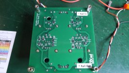
I can't see your image link. Won't load. On Eric's shunt board, I thought that R105, R110, and R112 are the positive rail values.
Edit: Sorry, R4, R7 and R8 are the positive rails. Values above. Your image finally loaded.
Edit: Sorry, R4, R7 and R8 are the positive rails. Values above. Your image finally loaded.
Last edited:
Clearly, either I've got a wrong component value in the wrong place, or one is damaged. I've double checked everything and compared the passive values with the positive rail and everything matches. I'm still only getting ~5v on pin 2 of IRF610 (Q103). I even replaced it, and replaced Q104 as well. Should be - according to the sim values - posted in Eric's schematic, ~ -22VDC. I even replaced the trimmer thinking it may be bad.
Verify Q104 that E and C pins are not shorted together since my simulations shows approximately the same voltage that you measure if I do so.
In case here are the simulated measurements points for +/- 24V outputs.
E and C pins not shorted, but replaced. Still nothing. Can't get past ~ -5.5VDC on negative rail. Urgh!
My best bet is to check the CCS.
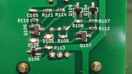
The 270R between source and gate of the JFET gives approximately 1.2mA ids current so around 330mV across R105, R110 and R112.
I would try first to replace Q105(my sim shows -4.2VDC output if Q105 is removed so pretty close of what you measure yourself).
The 270R between source and gate of the JFET gives approximately 1.2mA ids current so around 330mV across R105, R110 and R112.
I would try first to replace Q105(my sim shows -4.2VDC output if Q105 is removed so pretty close of what you measure yourself).
First check if the current in the CCS jfet are right. if they are low you can't adjust the output voltage correctly.
My best bet is to check the CCS.
The 270R between source and gate of the JFET gives approximately 1.2mA ids current so around 330mV across R105, R110 and R112.
I would try first to replace Q105(my sim shows -4.2VDC output if Q105 is removed so pretty close of what you measure yourself).
Quoting myself and eric 🙂
Last edited:
Q105 replaced. No change and still getting ~ -5.48v on output.
What should the voltage be on pin 2 (D) of IRF610 (Q103)? Shouldn't that be close to the output voltage of the negative rail? That ties directly to negative out.
What should the voltage be on pin 2 (D) of IRF610 (Q103)? Shouldn't that be close to the output voltage of the negative rail? That ties directly to negative out.
Could you post a pic? are you sure of the value of each component..and you measure also R5,R10,R12 voltage like you did with R105, R110 and R112 to compare with NRail
It is also better to check the IDSS of each Jfet before. If you use 2sk2099Gr you should have 2.6~6.5mA
IDSS classification from the datasheet >>Y: 1.2~3.0 mA, GR: 2.6~6.5 mA, BL: 6.0~14 mA
It is also better to check the IDSS of each Jfet before. If you use 2sk2099Gr you should have 2.6~6.5mA
IDSS classification from the datasheet >>Y: 1.2~3.0 mA, GR: 2.6~6.5 mA, BL: 6.0~14 mA
Is-it the board you power voltage reverse?
If so, you may also try to unsolder the electrolytics caps one by one starting with C104.
But before doing so, do verify there is no mistake with the passive resistors values if not done already.
If so, you may also try to unsolder the electrolytics caps one by one starting with C104.
But before doing so, do verify there is no mistake with the passive resistors values if not done already.
At this point all the MOSFeTs have been replaced and several of the 270ohm resistors. Still no change. I'm not sure what I'm getting crazier over; trouble-shooting this PCB with no positive results, or our US election and the aftermath in the news non-stop. I'm a bit of a political junkie too! 🙂 This hobby is suppose to help balance things out a little.
Attachments
Is-it the board you power voltage reverse?
If so, you may also try to unsolder the electrolytics caps one by one starting with C104.
But before doing so, do verify there is no mistake with the passive resistors values if not done already.
Power to the board is correct. I'm getting +- 40VDC after rectification and going into the shunt board. Haven't verified every resistor yet, but a few of 270ohm ones have been replaced including the 75K one.
It's correct. Thinking the same thing, I replaced it with one having correct marking. I had two different batches of SMDs, one with no marking that I had used.
Not this then! Damn.
I am a bit short of ideas to identify precisely which part is actually defective on this particular board.
I think you mentionned before that one board is working fine - correct?
Did you check the current limiter?
Across R103, you should have approximately 0.6v (0.63v according to my sim) and across R105 around 300mV.
If yes, it is probably safe to say this part including Q103 actually works OK.
Remark: I suggested before to remove C104 because if this part is defective and somehow leaky, you are also to get a very low output voltage as well according to my sims.
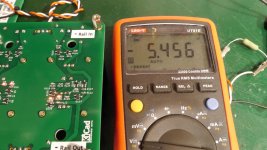
Across R103 I get 600mV
Across R105 I get 261mV
I replaced C104. The old one measure a bit low at 192mfd
Nothing changed. Still about -5.4V output.
My other board is not functioning either. That was the one with the mis-wiring and I haven't started trouble-shooting it yet. One at a time. 🙂
I know this is a worse case scenario and sounds crazy, but I'm prepared to remove all negative rail parts, clean the board and start over with new parts. At least SMDs remove easily! I have all the parts to do it. I bought extras!
Little steps... But still steps.
Finished milling the front plate after work.
Slim line 2U 280.


Finished milling the front plate after work.
Slim line 2U 280.
Last edited:

- Home
- Amplifiers
- Pass Labs
- UGS-muse preamp GB