Thanks for the discussion Bruno, it was very interesting, and thanks for your answers 🙂
All the best from Lars...
All the best from Lars...
Pierre,
Hmm.. I like this thread, and i found it's very informative about class D generally!
Come on guys, it's must go on. 😎
Hmm.. I like this thread, and i found it's very informative about class D generally!
Come on guys, it's must go on. 😎
Subjectively
To go beyond the numbers- what are some subjective differences. Not which is absolutely better, but what are some sonic differences. What speakers sound better with which amps. I have come to the conclusion that audio is somewhat of an artform of matching and mixing components for the desired results and that while one component may be perfect for one setup, it may sound horrible in another.
For example, I am using Magnepans in a relatively small room. Maggies can tend to sound bright and analytical in such a setup. Bass extension out of these dipoles is also somewhat limited. Therefore, I opted for the standard UcD 400 with Burr-Brown opamps because they have been described as "darker" and "smoother," while the AD8620 was more "bright" and "analytical." On a dynamic speaker (especially one with rolled off highs) or Maggies in a different room/setup (maybe a tube preamp to smooth things out), I'm sure that the AD8620 is better.
So, what mixes well with what? Which is better for low impedance speakers/complex loads? Overall impressions? Which sounds more tubelike? Which sounds more detailed? Which is brighter/darker? What is the sonic difference between variations of each? How would they work for a sub amp/mid amp/tweeter amp?
I personally love the way the standard UcD 400 sounds in my setup and feel glad I didn't get the AD8620s. However, as my room, components and speakers change, I may look somewhere else to find that balance...
RFI Spectrum Analyzer screenshots
(50 - 150 MHz, Center freq = 100 MHz)
Background noise shown on this shot:
ZAPpulse OFF
The peaks you can see are from the FM band. (National Danish radio stations).
And here with ZAPpulse on:
ZAPpulse ON
And just for comparison, the power wires of a normal hard drive:
Harddrive
(50 - 150 MHz, Center freq = 100 MHz)
Background noise shown on this shot:
ZAPpulse OFF
The peaks you can see are from the FM band. (National Danish radio stations).
And here with ZAPpulse on:
ZAPpulse ON
And just for comparison, the power wires of a normal hard drive:
Harddrive
Re: RFI Spectrum Analyzer screenshots
What's the scale? ie. where is 3uA?
Yesterday's discussion sparked a whole overhaul of the hypex web site 🙂 we'll have all the plots that are now only in the folders put up on the site as well.
What's the scale? ie. where is 3uA?
Yesterday's discussion sparked a whole overhaul of the hypex web site 🙂 we'll have all the plots that are now only in the folders put up on the site as well.
Lars, the metal is Ni which also is magnetic. I doubt very much that iron is used.Lars Clausen said:...., check if the leads are iron or copper. Those with copper leads sound much better than those with iron leads (most brands).
Re: RFI Spectrum Analyzer screenshots
What happens at lower frequencies, say from 100kHz to 10mHz??? The ZAP switches at 400kHz or so, so 400kHz and its harmonics are much lower in frequency range than you have shown plots of.
What I know is that when I had the ZAPs, during switch off, I got lots of whining sounds and even radio reception via the ZAP, so the ZAP picked up some radio waves and transformed them to audible sound (probably AM modulated radio signals). With the UcD I don't have that. If I put my ears in the tweeters and listen very very carefully during switch-off, I can hear a very very distant soft whining sound of the UcD (similar to what the ZAP did but probably about 30-40dB lower in level). This indicates to me that the EMI/RFI issues with the UcD modules are better controlled. It seems the UcD designers have taken extreme care to reduce EMC/RFI issues. Also 2 UcD close to eachother in the same case is no issue at all, no problem at all with interference.
I think one of the issues with the ZAP is the output filter coil. Although I like the looks of that coil, looking very robust and overdimensioned and with a nice solid teflon isolated wire, it is connected to the PCB with pretty long wires that can radiate. Then the coil has an airgap at the outside which will also radiate. Making your PCB a little larger (probably you don't like that since it would become bigger than a credit card) would allow you to mount the coil on board with much shorter wires. Seems that having solid power supply decoupling on boards is also important as that is what the UcD designers are doing, they even add inductors in the power rails to reduce HF leakage via the power rails. I think earlier ZAPs had that as well but they were removed to avoid the "piano" distortion (read that sometime ago on your web-site). With good coils, that should not be an issue as I don't hear it with UcDs.
Maybe you could look into these issues as I think there are more ZAP users that had issues that were EMI/RFI related.
Best regards
Gertjan
Lars Clausen said:(50 - 150 MHz, Center freq = 100 MHz)
Background noise shown on this shot:
ZAPpulse OFF
The peaks you can see are from the FM band. (National Danish radio stations).
And here with ZAPpulse on:
ZAPpulse ON
And just for comparison, the power wires of a normal hard drive:
Harddrive
What happens at lower frequencies, say from 100kHz to 10mHz??? The ZAP switches at 400kHz or so, so 400kHz and its harmonics are much lower in frequency range than you have shown plots of.
What I know is that when I had the ZAPs, during switch off, I got lots of whining sounds and even radio reception via the ZAP, so the ZAP picked up some radio waves and transformed them to audible sound (probably AM modulated radio signals). With the UcD I don't have that. If I put my ears in the tweeters and listen very very carefully during switch-off, I can hear a very very distant soft whining sound of the UcD (similar to what the ZAP did but probably about 30-40dB lower in level). This indicates to me that the EMI/RFI issues with the UcD modules are better controlled. It seems the UcD designers have taken extreme care to reduce EMC/RFI issues. Also 2 UcD close to eachother in the same case is no issue at all, no problem at all with interference.
I think one of the issues with the ZAP is the output filter coil. Although I like the looks of that coil, looking very robust and overdimensioned and with a nice solid teflon isolated wire, it is connected to the PCB with pretty long wires that can radiate. Then the coil has an airgap at the outside which will also radiate. Making your PCB a little larger (probably you don't like that since it would become bigger than a credit card) would allow you to mount the coil on board with much shorter wires. Seems that having solid power supply decoupling on boards is also important as that is what the UcD designers are doing, they even add inductors in the power rails to reduce HF leakage via the power rails. I think earlier ZAPs had that as well but they were removed to avoid the "piano" distortion (read that sometime ago on your web-site). With good coils, that should not be an issue as I don't hear it with UcDs.
Maybe you could look into these issues as I think there are more ZAP users that had issues that were EMI/RFI related.
Best regards
Gertjan
Bruno: 3 uA RMS is about 2 div. (On the bottom, the next 2 div are 30 uA etc).
Ghemik:
My spectrum analyzer only woorks from 2 MHz to 1 GHz. So i can't tell you much about 0 - 2 MHz. From 2 - 10 MHz though, only background noise.
All the best from Lars
Ghemik:
Also no problem with ZAPpulse ...Also 2 UcD close to eachother in the same case is no issue at all, no problem at all with interference.
With some of the early versions, yes, but not for the last couple of years. Which versions have you been working with?Maybe you could look into these issues as I think there are more ZAP users that had issues that were EMI/RFI related.
My spectrum analyzer only woorks from 2 MHz to 1 GHz. So i can't tell you much about 0 - 2 MHz. From 2 - 10 MHz though, only background noise.
All the best from Lars
Lars Clausen said:Bruno: 3 uA RMS is about 2 div. (On the bottom, the next 2 div are 30 uA etc).
So the analyser noise is around 0.3uA?
I forgot to mention that we test with the amplifiers delivering a substantial amount of power to catch diode recovery problems etc as well. What power are your DUT running at?
Bruno: i would say a little higher, the noise floor seems to be in the middle of the div where 0.3 uA is the lower line. It's hard to know what is analyzer noise, and what is incoming background noise, when you don't use a TEM cell or RF screened room.
Lars Clausen said:Bruno: 3 uA RMS is about 2 div. (On the bottom, the next 2 div are 30 uA etc).
Ghemik:
Also no problem with ZAPpulse ...
With some of the early versions, yes, but not for the last couple of years. Which versions have you been working with?
All the best from Lars
Hi Lars,
I had 2.2SE and I had trouble to keep the modules silent with two of them mounted close to each other running of the same supply (predator). Did everything that was written in the cookbook. I think (but it was quite a while ago) that I got the best results using each module on a seperate supply and keeping them away from eachother.
I think your newer 2.3SE switches off before the rail voltage gets too low so the whining sound and radio reception stuff are not audible anymore. However, does that mean that the root-cause of those EMI related noises has been solved as well?
I guess that the low frequency signal at the outputs during switch off (due to the DC servo circuit???) is now gone as well? This would make the modules more suitable for active systems when no passive x-over is used, so that is a clear improvement.
Best regards
Gertjan
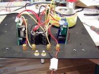
UCD400 and UCD400AD RFI emissions
Jan and Bruno sent me their newest modules, to make a comparing EMI measurement on my spectrum analyzer. 🙂 Thanks Jan and Bruno!
I made all measurements (also the ones for ZAPpulse) with a Ferrite click on tube. (To stop airborne induced noise jumping into the speaker wires).
RFI for UcD400 (first version serial no. 0001 😀 )
UDC400
RFI for UcD400AD (Newest version)
UDC400AD
The RFI is greatly reduced on the newer version compared to the first versions of UcD400.
For comparison:
RFI for ZAPpulse 2.3SE
ZAPpulse 2.3SE
The same setup was used for all measurements.
See the setup here:
Attachments
Re: UCD400 and UCD400AD RFI emissions
Yeah the original 400 was a minor disaster due to the inductor.
Looking forward to getting your 2.3 modules in return so we can duplicate the test.
Do you also have a pic of the setup that you used to test the zap module?
In the meantime, any chance you could do the test once more with both amplifiers delivering power?
OK i went ahead and did them (seems to be more interesting than starting the weekend 😀 )
20 V RMS out in a simulated load with RCL (like a speaker). 50 Watts RMS
It looks like it's a tie .....
UCD400 with 20 V RMS
ZAPpulse with 20 V RMS
20 V RMS out in a simulated load with RCL (like a speaker). 50 Watts RMS
It looks like it's a tie .....
UCD400 with 20 V RMS
ZAPpulse with 20 V RMS
Hello,
I was one week on vacation, sorry for the alte reply. Lars we have also received the Zappulse 2.3, thank you.
Hereby my measurement results on the two amplifiers. We have an Advantest R3131A spectrum analyzer and a current clamp.
Actually I measure much more EMI.......
Jan-Peter
I was one week on vacation, sorry for the alte reply. Lars we have also received the Zappulse 2.3, thank you.
Hereby my measurement results on the two amplifiers. We have an Advantest R3131A spectrum analyzer and a current clamp.
Actually I measure much more EMI.......
Jan-Peter
Attachments
What were the conditions for the first measurement?
What about spectrum from 1 MHz and up? Just wondering.
Any picture of the measurement setup? Also wondering about that.
What about spectrum from 1 MHz and up? Just wondering.
Any picture of the measurement setup? Also wondering about that.
Peranders, the first measurement was in standby mode and a load of 8 connected to the amplifier. Spectrum Analyzer from 30MHz to 150MHz.
Hereby a measurement of the outputsignal by the Scope (Fluke- PM3391A), againe with 8 ohm and 100W of output power.
Jan-Peter
Hereby a measurement of the outputsignal by the Scope (Fluke- PM3391A), againe with 8 ohm and 100W of output power.
Jan-Peter
Attachments
What is the main difference between ZAP and UcD, is it the switching frequency or filtering or both?
- Status
- Not open for further replies.
- Home
- Amplifiers
- Class D
- UCD400 or ZAPPulse?