The filter's physical cut-off frequency is 35kHz (L=30uH, C=680nF).peranders said:What is the main difference between ZAP and UcD, is it the switching frequency or filtering or both?
Because the filter is inside the loop, it only determines power bandwidth. Small-signal bandwidth is determined solely by the loop. Trusting nobody needs more than 35kHz full-power, this allows for better filtering of the carrier. The loop will take care of keeping the filter from affecting the audio.
The switching frequency of UcD is set at around 400kHz. A notable difference between UcD and other self-oscillating systems is that the switching frequency modulates per 1-M^4 (M the modulation index between -1 and 1), so that even near clipping the switching residual remains constant in amplitude. In other self-oscillating amps, the switching frequency drops more quickly, along 1-M^2. Near clipping, the residual becomes larger and larger. This is not as big a problem as it looks on an oscilloscope picture, but the sound of such an amplifier clipping is quite recognisable. Some plots are provided on the UcD paper on the hypex site.

I'm beginning to understand what it is that people are describing as the "lively top-end" of the Zap modules.Jan-Peter said:Hereby a measurement of THD versus Frequency of Zap and UcD;
(note: I'm located 350km south of where JP is, so I'm following this on the forum too)
Jan-Peter said:Hereby a measurement of THD versus Frequency of Zap and UcD;
Jan-Peter
Hi Jan-Peter,
Thanks for sharing all those graphs. Next would be nice to see how the frequency response of both UcD and ZAPpulse compare when both are loaded with a typical speaker. Also step response (square waves) would be nice to see.
Best regards
Gertjan
Originally posted by Jan-Peter:
Actually I measure much more EMI.......
Well if you look closer on your graphs, most of your noise is just below -60 dB, and most of ours is below - 50 dB. I would say the difference is something like 6-10 dB. I will not dispute your measurements, but i just want to ask if you have followed our RFI recommendations? (look here)
and better drawing is found here
In any case i found that incorrect hookup can mean a great difference in the noise emissions from our ZAP module, because we operate with a floating input GND. If this is not properly tied to GND, (As shown in the above link) the noise emission will grow significantly.
Anyway we are in progress with CE certification, and i will make some real TEM cell RFI emission tests of our modules in the certified RFI lab very soon. I will post results here later.
About the THD, there is nothing new here, your THD specs have always been lower than ours. As always, the way we see it, we could easily lower our THD, but not without sacrificing some of the high sound quality. Which has recently been confirmed by independent listening panels.
No doubt if your main interest as a customer is to get an amplifier with good THD spec's you should definitely choose Jan-Peter's amplifier over ours. Or even Icepower, which has very low THD spec also).
Here's a case of 'ugly' speaker impedance behaviour. The culprit in this case is the oldish Infinity Kappa9, I have Infinity Reference Standard II, which has a similar impedance curve at around 87dB or so 1W/1m. Such speakers eat AB class amps for breakfast, but even the UcD180 seems to hold its pants quite respectably and sounds better than massive AB units I've tried.
speaker impedance curve
Question is what will be the influence of amplifier output impedance in the different cases (post/pre filter NFB) on frequency response on such a devilish load? Or, UcD or Zap for this one?
An externally hosted image should be here but it was not working when we last tested it.
speaker impedance curve
Question is what will be the influence of amplifier output impedance in the different cases (post/pre filter NFB) on frequency response on such a devilish load? Or, UcD or Zap for this one?
Originally posted by Lars;
Well if you look closer on your graphs, most of your noise is just below -60 dB, and most of ours is below - 50 dB. I would say the difference is something like 6-10 dB. I will not dispute your measurements, but i just want to ask if you have followed our RFI recommendations? (look here)
and better drawing is found here
Of course NOT, it's a one to one comperation and not measuring one without any one with extra shielding. Or an amplifier what is tweaked for an EMI certifaction.......
The both amplfiers were mount on an aluminium plate and all power wires are put true a current clamp. So actuall we measure the HF antenna current.
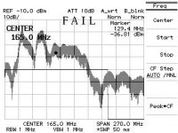
We have done a lot of official measurements so we know below which level we must be to be on the safe side. When you look back to the Spectrum Analyzer measurement you have to be around -60dBM of the screen, in this case you have big chance you pass all EMI rules....
In our internal demo 19", were we have the advantage of a complete metal case, the EMI measurent in an official test is really VERY low.
Two weeks ago I have measured an other Class-D amplifier, and this amp was really something different. This product is sold in the US and Europe.
Please have a look;
Jan-Peter
Attachments
We could easily furnish our modules with the same recommendations, and get a similar improvement on EMI on top of what they already do. However, as you know, our modules are designed to be the ideal "drop-in" replacement for linear amplifiers, so we prefer not to rely on users having to take special precautions.Lars Clausen said:I will not dispute your measurements, but i just want to ask if you have followed our RFI recommendations?
Now now, Lars 😀Lars Clausen said:About the THD, there is nothing new here, your THD specs have always been lower than ours. As always, the way we see it, we could easily lower our THD, but not without sacrificing some of the high sound quality.
1% THD at higher frequencies exceeds that of most good tweeters and is plainly audible, manifesting itself as a very obvious brightening of the top end. I am in no doubt that many people will like this sound, but an amplifier should not have a sound of its own like that.
Lars Clausen said:No doubt if your main interest as a customer is to get an amplifier with good THD spec's you should definitely choose Jan-Peter's amplifier over ours.
You seem to believe I design for the best numbers. This is not quite the case. If I did, the amplifier would have had a rising THD vs frequency response (0.003% at 1kHz, 0.03% at 10kHz). This would have resulted in a spectacular THD vs power graph at 1kHz, which is what numbers-minded people are looking for.
My design algorithm is quite different:
1) By ear, find out which measured performance criteria matter, and which don't. Define a performance spec based on this.
2) Run through the maths to find out the required design parameters. Design accordingly.
3) Verify that the hardware indeed performs as predicted by the maths (and hence, as required by the spec). If the hardware performs worse (or even better) than what was predicted under 2, check what happened.
4) If the customer is willing to pay for it, select components by ear. Most "component effects" don't show up very clearly, if at all, in measurements, but they are most clearly audible.
In step 1, it is important to start listening with "unbiased ears". The ultimate goal is to create a design which is "transparent", meaning not adding or hiding information -this includes emotion in the music- and not modifying the perceived tonal balance, sound staging etc.
It is all too easy to take a liking for a certain "sound" (especially as brought forth by hardware one built oneself!), thus shifting away from that target.
Listening experiences with equipment other than power amplifiers is crucial in learning to identify colourations. For instance, I also design AD/DA converters. There, testing for transparency is shockingly easy: loop through and compare with the original audio. It's amazing how often the signal comes out sounding "better" than the original, at least on some counts. If you happen to have a pair of dCS's lying about, listen what they do to the stereo image and you'll know what I mean.
With a power amplifier unfortunately, you can't take it out of the chain and listen to what the input signal sounds like on its own. Using other power amplifiers as reference is hardly more than a band-aid to this problem. However, having learnt to recognise types of colouration in other types of equipment in back-to-back tests, it now becomes quite easy to recognise them in power amplifiers, and thus determine whether a power amplifier deserves the label transparant or not.
The outcome of such listening tests appears two-fold.
On one side there are so-called "mysterious" effects related to component parts like capacitors etc that we audiophiles are often held up to ridicule for because we don't "have data". Too bad, but I prefer to trust my ears there. Unfortunately, this ridicule has resulted in audiophiles taking up the complete converse position, namely to dismiss measured performance as something wholly irrelevant to perceived sound.
Just like the "meter readers" are deluding themselves into not hearing what difference a capacitor can make, many audiophiles are turning a deaf ear to what measured distortion means to the sound. In earlier days, I too disregarded measurement because "there was so much to hear that you couldn't measure". Now, already from a purely logical prespective this reasoning is flawed: A->B does not mean B->A. In other words, the converse isn't true. Looking back, this is obvious. While a certain test method can miss things which are nevertheless there, when it does turn something up, it's certain to exist. Indeed, I found there are a lot of things to "sound" that are easy to measure and hence, model mathematically. This is good news, because all of these things are now solidly in the engineering domain. Simplifying things a bit, an amplifier should have frequency-invariant behaviour. Amplitude, distortion, noise etc all should be independent of frequency. Proponents of zero-feedback amplifiers already have an intuitive grasp of this, though many might not have expected things to be this plain. Furthermore, THD above 0.05% introduces colouration, though not necessarily bad sounding.
On the other side, there are the bits that "are not measurable", but that do matter, and that are invariably related to certain components with similar specs but vastly different sound. Until measurements are found to identify these parameters, this is sorted out in step 4, during subsequent listening tests.
Process 2-3 is iterative, and is indeed pure engineering, with not a loudspeaker in sight. In practice, class D amplifiers are more amenable to mathematical prediction than linear amplifiers.
Step 4 is component choice. I'm not making a secret of the fact that the stock UcD modules have not gone through stage 4 at all, for the simple reason that for most customers they already sound more than good enough. We're not planning to double our product range to entail both "standard" and "tuned" modules. This would not be economical. Besides, DIY folk tend to be avid tuners themselves. Customising the sound to one's own liking is part of the fun. But, "make no mistake about it," I have listened to more capacitors, resistors, transistors, chips, cables and what have you than I care to remember.
I'd like to emphasise that "measurable" and "unmeasurable" (but both audible) effects are not fixed and mutually exclusive domains. Far from it. The art & science of audio engineering is all about moving as many things from the latter to the former domain by devising new or more accurate test methods.
May I suggest measuring these modules at higher power levels and higher frequencies? Of course, it depends what on one's standards what "very low THD" means.Lars Clausen said:Or even Icepower, which has very low THD spec also).
Hello,
the measurements were very impressive and the statements were interesting too.
Thank you very much for that!
Timo
the measurements were very impressive and the statements were interesting too.
Thank you very much for that!
Timo
Or even Icepower, which has very low THD spec also.
Maybe......depending on which one you look at. Not to mention their EMI. But they do not sell to DIYers, so the point is moot.
KM may try to sell you some of his that he has left over.................but........
Jocko
Jan-Peter said:
Two weeks ago I have measured an other Class-D amplifier, and this amp was really something different. This product is sold in the US and Europe.
Please have a look;
Jan-Peter
Nuforce?
Just came across this little graphic. Maybe it is an old one, but I'll post it anyway.
BTW. I do not agree to that picture at all.
It is taken from B&O icepowers website.
An externally hosted image should be here but it was not working when we last tested it.
BTW. I do not agree to that picture at all.
It is taken from B&O icepowers website.
....he, he, time has passed.  Class D and ICEpower, what's the difference really? And class B is better than class D... before maybe.
Time to redraw the picture, B&O, competitors are catching up.
Class D and ICEpower, what's the difference really? And class B is better than class D... before maybe.Time to redraw the picture, B&O, competitors are catching up.
Just wondering, but those measurements you have made are there any special considerations taken due to ZAP's special output?Jan-Peter said:Hereby a measurement of THD versus Frequency of Zap and UcD;
Jan-Peter
The danish magazine High Fidelity tested Lars' modules and the results was extremely bad but mostly due to measurement methods I think. The question was how to interpret the measurements.
Maybe it's the same thing here that the audio coming from Lars' modules are better than measurements give a hint of?
The Zap output is in no way more "special" than any other class D's, except that the output ripple is unusually large.peranders said:Just wondering, but those measurements you have made are there any special considerations taken due to ZAP's special output?
In order not to be influenced by switching ripple, the AP is fitted with an AES17 input filter that rejects anything above 20kHz. Further, if any HF did make it past any input filtering, this would show up as noise, not as distortion.
Also, the EMI level of the Zap is way too low to cause erroneous analyser readings. The amplifier shown as an example of "really bad EMI" produced much lower THD readings than the Zap modules, demonstrating that THD can still be reliably read in the presence of EMI much higher than what either Zap or UcD produce.
In other words: the distortion plots show actual distortion that is really there. It is not a measurement problem.
The only way forward from here to reducing distortion is switching faster by the same factor. All other things equal this also increases EMI by the same amount. Yet, switching faster is exactly what UcD does. To arrive at the low EMI levels that we are getting, an extreme amount of attention to detail was required.
I'll guess you have put much work into getting a precise switching with full control over switch times and dead times.
Shootout at our local hifi circle meet
OK it was hardly a fair shootout, but I brought both my UCD400 based amps and my Zappulse 2.2SE based amps to the local London hifi circle home meet.
We had some technical issues early on when the hosts speakers got melted! (before my amps went anywhere near them), but by chance there was a boot sale over the road and a pair of old B&W speakers were on offer at £15!! Actually they sounded rather good to be honest, and so we wired them up to the two class D amps for a bit of a listening test.
The general consensus was that the UCD400 amps were slightly preferred by most people. I did hear at one voice mention they preferred the Zappulse sound early on, but not sure if that was still true by the end of the test. Worth mentioning was that one person reported the Zappulse loosing control a little during the busier parts of one track...
The powersupplies are NOT identical in each amp. The UCD400 uses 10,000uf per rail per module (BC 056?) plus 1Kva torroid. The zappulse 2.2SE uses a single predator PSU board with 15,000uF per rail per module (2 extra caps outboard of the predator basically) of Nippon Chemicon caps, plus another 1Kva torroid. Both have a shared PS for both modules and otherwise similar parts like softstart, DC filter, etc. You can find pictures of both amps if you search these forums I think.
So possibly the UCD400 has the weaker powersupply, but appeared to be preferred in this little test which involved speakers of no great value.
However, the audience were mainly valve amp nuts who would mostly never entertain listening to a transistor amp. So when I say that they were ALL universally impressed with BOTH of these amps then I think this is high praise indeed for both of them. I took a lot of questions about both amps and possibly they will turn into some sales...
So in conclusion both types of module showed an ability to turn pretty marginal speakers into REALLY decent sounding transducers and got really, really good reviews. In *this* test the UCD400 was slightly preferred to the Zappulse - but both were clearly very good.
- Status
- Not open for further replies.
- Home
- Amplifiers
- Class D
- UCD400 or ZAPPulse?