kittikun said:As I know, the small film cap will help reducing high frequency noise from the supply in which the big electrolytic could not get rid of it.
That's the simple version. To get a more complete view of what happens, make a simulation using detailed electrical models including parasitic inductance.
At very high frequencies, small caps can help shunt the parasitic inductance, but at intermediate frequencies, you get a resonant circuit.
Since UcD modules don't need the extra filtering (there is further filtering on the modules), you can dispense with adding caps across the large tanks.
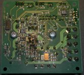
Could someone post a nice clear picture of the full top & full bottom of the UCD 180ad module? Want to see what it looks like for mod purposes.
Also can the UCD 180 be run with a 300VA - 27.5V transformer?
Thanks in advance.
Also can the UCD 180 be run with a 300VA - 27.5V transformer?
Thanks in advance.
Bruno or JP
For the UCD 180 AD module. Could you please verify the following cap values for me:
1. Two low voltage decoupling caps - 22uf 50v ?
2. Output filter cap - .68uf 63v ?
3. Boot strap cap - values ?
Thanks
For the UCD 180 AD module. Could you please verify the following cap values for me:
1. Two low voltage decoupling caps - 22uf 50v ?
2. Output filter cap - .68uf 63v ?
3. Boot strap cap - values ?
Thanks
Stevenacnj said:For the UCD 180 AD module. Could you please verify the following cap values for me:
1. Two low voltage decoupling caps - 22uf 50v ?
2. Output filter cap - .68uf 63v ?
3. Boot strap cap - values ?
1a) There are two 22u 50V caps which are coupling caps (C7/C8), and are directly in the signal path between the buffer op amp and the modulator.
1b) There are also two 22u 63V caps close to the heat sinks (C35/C36). They are damping caps to prevent resonance among C32/C33 and C23/C28. They have the full supply voltage across them. Value is not critical, but ESR is (not too low!)
2) 0.68uF 63V. Not lower than 63V. Do not use caps that are physically much larger. Otherwise the parasitic inductance might well defeat the purpose of the filter at radio frequencies.
3) 220uF, 16V.
I would suggest shorting C7/C8, and using high-quality film caps externally, before the input of the module. The input impedance of the module is much higher than the impedance seen by C7/C8 so at the input you can use a more practical value (e.g. 1uF).ackcheng said:Any downside for replacing the 22uF with good quality film type?
PS: It is sufficient to ask the question in only one thread.
Thanks! The other post on the neighbouring thread is deleted.
I guess you mean
+in --> 1Uf cap --> +in lead on board
-in --> 1Uf cap --> -in lead on board.
If I use unbalanced input, do I still need 2 caps?
I guess you mean
+in --> 1Uf cap --> +in lead on board
-in --> 1Uf cap --> -in lead on board.
If I use unbalanced input, do I still need 2 caps?
Bruno
"1b) There are also two 22u 63V caps close to the heat sinks (C35/C36). They are damping caps to prevent resonance among C32/C33 and C23/C28. They have the full supply voltage across them. Value is not critical, but ESR is (not too low!)"
Could I use a 10uf 63V low ESR for C35 & C36?
Thanks
"1b) There are also two 22u 63V caps close to the heat sinks (C35/C36). They are damping caps to prevent resonance among C32/C33 and C23/C28. They have the full supply voltage across them. Value is not critical, but ESR is (not too low!)"
Could I use a 10uf 63V low ESR for C35 & C36?
Thanks
Correct. One inserts the coupling caps before J7/J1 (UcD180/400).ackcheng said:I guess you mean
+in --> 1Uf cap --> +in lead on board
-in --> 1Uf cap --> -in lead on board.
No.ackcheng said:If I use unbalanced input, do I still need 2 caps?
Correct.ackcheng said:I presume C7/C8 in UCD180 is the same as C23, c24 in UCD400?
No please no low ESR. ESR should be around 0.5 ohms! ESR is used here for damping. If it is too low, there will be no damping. One should view the C35/C36 capacitor as a snubber with built-in series resistance. The characteristic impedance of the resonance between the inductance of the "main" caps (470u) and the ceramic caps (100n) is similar in value to the ESR of standard electrolytics in the 4.7uF...47uF range (depends on type). Using too good electrolytics would defeat the purpose.Stevenacnj said:Could I use a 10uf 63V low ESR for C35 & C36?
To understand what I mean, look at the switching waveform with/without C35/C36 installed. When they are not installed, you will find some 100mV of 2MHz ripple on the switching waveform. If you want to experiment with different capacitor types, you now know what to look for: the capacitor should damp this resonance completely.
I'm aware that many other class D amplifiers do not go into such detail, but when you're really shooting for the lowest possible EMI, such a 2MHz ringing, even at 100mV or so, becomes significant. Besides, ringing at such relatively low frequencies causes high-order distortion (admittedly not a lot).
Matjans,
Thanks for the bottom pic.
Yeah board looks burned .
.
Could you be so kind as to post a nice centered close pic (like you did for the bottom) of the top?
I have my UCD 180AD modules on order & I just want to get a good sense of the layout.
Thanks
Thanks for the bottom pic.
Yeah board looks burned
.Could you be so kind as to post a nice centered close pic (like you did for the bottom) of the top?
I have my UCD 180AD modules on order & I just want to get a good sense of the layout.
Thanks
Bruno!
Very well said! And this explanation of Yours should also be made very clear on the other thread, too [hotrodding the ucd..]. I've been smelling trouble since the people started to play with that power bypass structure, that is, exchanging the main power caps [470uF]!
It should be made very clear that those caps make part of a refined optimization process, and by changing them one upsets the original balance.
I would have a question, also. The original problem arises from the series resonant nature of the smaller bypass element - the ~100nF ceramic cap. This part is usually viewed upon like a high efficiency, low ESL, low ESR bypass element. On the other hand, it can be taken like a high Q series LC resonant circuit. In this point of view it's low ESR is rather a nuisance than a real benefit. [because of the high Q, you can use it's low ESR only in a very narrow band]. Now, if you would eliminate it's high Q in the first place, by increasing it's ESR to about .2 ohm, by adding a small SMD external resistance?
A value at around that would help in eliminating[damping] the impedance peaking with the 470uF's ESL, AND would dampen the self-resonance, as well. While the first effect is the same like what you can get with the parallel - snubbing - 22uF, the second effect vill broaden the second resonance, and this way extending the HF response, too?
from my network analyzer tests, I know for sure that this is really what is happening, and in this way it is possible to get a smooth & extended, low value resistive type bypass configuration. The part that I'm not sure of is how important in the reality [of a working circuit] that narrow band low ESR range? Then how much power will be dissipated in that additional resistor? [that is, how small it can be made?] Then, how much extra stray inductance will be generated by it's inclusion in the topology?
I'm asking You, because I suppose you been playing with these things..
Ciao, George
No please no low ESR...
Very well said! And this explanation of Yours should also be made very clear on the other thread, too [hotrodding the ucd..]. I've been smelling trouble since the people started to play with that power bypass structure, that is, exchanging the main power caps [470uF]!
It should be made very clear that those caps make part of a refined optimization process, and by changing them one upsets the original balance.
I would have a question, also. The original problem arises from the series resonant nature of the smaller bypass element - the ~100nF ceramic cap. This part is usually viewed upon like a high efficiency, low ESL, low ESR bypass element. On the other hand, it can be taken like a high Q series LC resonant circuit. In this point of view it's low ESR is rather a nuisance than a real benefit. [because of the high Q, you can use it's low ESR only in a very narrow band]. Now, if you would eliminate it's high Q in the first place, by increasing it's ESR to about .2 ohm, by adding a small SMD external resistance?
A value at around that would help in eliminating[damping] the impedance peaking with the 470uF's ESL, AND would dampen the self-resonance, as well. While the first effect is the same like what you can get with the parallel - snubbing - 22uF, the second effect vill broaden the second resonance, and this way extending the HF response, too?
from my network analyzer tests, I know for sure that this is really what is happening, and in this way it is possible to get a smooth & extended, low value resistive type bypass configuration. The part that I'm not sure of is how important in the reality [of a working circuit] that narrow band low ESR range? Then how much power will be dissipated in that additional resistor? [that is, how small it can be made?] Then, how much extra stray inductance will be generated by it's inclusion in the topology?
I'm asking You, because I suppose you been playing with these things..
Ciao, George
The resonance we're seeing is not the series resonance of the chip cap itself, but the parallel resonance of the chip cap and the trace+lead inductances of the "large" elcaps.
Because of that, the damping resistance is higher than what you would need for damping only the series resonance of the chip cap itself (which is quite academic btw, because there is also trace inductance, including the newly added damping resistor), which in turn implies you are throwing away more decoupling performance than the original analysis suggested.
What would work better from an RFI perspective is inserting a series resistance in the power line after the 470u cap. Unfortunately, this would really incur a lot of losses! Next you could make this a parallel LC circuit to function as an inductive series snubber to get rid of most of the losses. Arguably this solution would work quite nicely, though the rise in total impedance at the power stage would cause distortion.
(btw: only RF circuits actively count on the series resonance of decoupling networks. I've never seen it actively used anywhere else)
Bruno,
Also I was talking about the same thing, though You are right, I did not
formulate my statement clearly enough.
In the above I was talking about the first - parallel -impedance PEAK, and then the second -series - impedance DIP. Also You are right in that none of these resonances are attributes of the participating parts only - one should take into account all the stray inductances / capacitances. But inserting a series R help lowering the Q, and this broadens [flattens] both the peak & dip, as well. And it's the more flat DIP which might be a bit extra, with respect to the "snubber".
I will try to illustrate it later on, not only for pushing my point of view, but because I find it a little interesting particular, which -maybe- could even be useful. And I'm disturbing You with it, because I feel it's exactly in this application where it can mean some difference. And You are the one with the real experience here.
Ciao, George
Also I was talking about the same thing, though You are right, I did not
formulate my statement clearly enough.
A value at around that would help in eliminating[damping] the impedance peaking with the 470uF's ESL, AND would dampen the self-resonance, as well.
In the above I was talking about the first - parallel -impedance PEAK, and then the second -series - impedance DIP. Also You are right in that none of these resonances are attributes of the participating parts only - one should take into account all the stray inductances / capacitances. But inserting a series R help lowering the Q, and this broadens [flattens] both the peak & dip, as well. And it's the more flat DIP which might be a bit extra, with respect to the "snubber".
I will try to illustrate it later on, not only for pushing my point of view, but because I find it a little interesting particular, which -maybe- could even be useful. And I'm disturbing You with it, because I feel it's exactly in this application where it can mean some difference. And You are the one with the real experience here.
Ciao, George
Bruno Putzeys said:
No please no low ESR. ESR should be around 0.5 ohms! ESR is used here for damping. If it is too low, there will be no damping. One should view the C35/C36 capacitor as a snubber with built-in series resistance.
I have ordered Elna Silmics and plan to try these C35/C36. But can not found ESR spec in their datasheet http://www.elna.co.jp/en/ct/pdf/ROSe.pdf. Do somebody know what is ERS of Silmics or can it be calculated somehow from other specs?
How about ESR in 470uF caps. Should it be also not too low?
Do Silmic have suitable ESR for that cap?
Pasi P said:I have ordered Elna Silmics and plan to try these C35/C36. But can not found ESR spec in their datasheet http://www.elna.co.jp/en/ct/pdf/ROSe.pdf. Do somebody know what is ERS of Silmics or can it be calculated somehow from other specs?
How about ESR in 470uF caps. Should it be also not too low?
Do Silmic have suitable ESR for that cap?
I recall the Silmics have a normal ESR, nothing special, and therefore suited to the application 😀. There's another post in this thread where I measured a selection of caps including silmics.
The ESR of the 470uF cap is not extremely critical, owing to the 22uF "damping" caps.
I might note that so far in all equipment I've modded that had silmics in them, I consistently ended up chucking them out in favour of cerafines or (now obsolete) BC 035 series. The silmics greatly overemphasise the highs. Probably "hi-fi" to some, but cheap coloration to my ears.
- Home
- Amplifiers
- Class D
- UCD180 questions