Gertjan,
It's post 493 of that page, I've tried to describe how I would measure impedance without the analyzer.
Ciao, George
It's post 493 of that page, I've tried to describe how I would measure impedance without the analyzer.
Ciao, George
DC-protection of UCD:s have been discussed earlier but i have not found good ready-built solution yet.
I want disconnect power supply lines and using dual mono.
Will this circuit be ok?
http://sound.westhost.com/project33.htm#tests
I want disconnect power supply lines and using dual mono.
Will this circuit be ok?
http://sound.westhost.com/project33.htm#tests
UcD without opamp
Hi Bruno (or whoever it may concern)
Wouldn´t it be rather easy to get rid of the input OPamp?
If you put a 2K2 resistor across the noninverting input of the comperator, an equal Z of the two inputs should be the result?😕 😱
As the gain is only 6db it would be fairly easy to compensate in the preamp..
Koldby
Joseph K said:Gertjan,
It's post 493 of that page, I've tried to describe how I would measure impedance without the analyzer.
Ciao, George
Hi George,
Thanks, I'm doing something similar. My scope has a built in arbitrary function generator and input/output are only a few cm away from eachother. I have not used 50Ohm termination as the line is very short. I have used square waves but I can try frequency sweeps as well. I used a 100Ohm resistor in series with the output to inject a current into the caps and measure the voltage over the caps.
Thanks and best regards
Gertjan
Re: UcD without opamp
The UcD circuit should be seen as a differential amplifier with 1.8k for the two imput resistors and 8.2k for the two feedback resistors. The input impedance at the noninverting input is 1.8k+8.2k=10k referenced to ground. The input impedance at the inverting input is 1.8k+8.2k=10k referenced to the speaker output. The latter works out as 1.8k referenced to a virtual source of Vin(noninverting)*8.2k/(8.2k+1.8k). In other words, the input impedance cannot be balanced by adding resistors referenced to ground.
The gain of the op amp section is 5 (14dB). If your preamp will drive the modulator directly, the op amp can be skipped.koldby said:Wouldn´t it be rather easy to get rid of the input OPamp?
If you put a 2K2 resistor across the noninverting input of the comperator, an equal Z of the two inputs should be the result?😕 😱
As the gain is only 6db it would be fairly easy to compensate in the preamp..
The UcD circuit should be seen as a differential amplifier with 1.8k for the two imput resistors and 8.2k for the two feedback resistors. The input impedance at the noninverting input is 1.8k+8.2k=10k referenced to ground. The input impedance at the inverting input is 1.8k+8.2k=10k referenced to the speaker output. The latter works out as 1.8k referenced to a virtual source of Vin(noninverting)*8.2k/(8.2k+1.8k). In other words, the input impedance cannot be balanced by adding resistors referenced to ground.
Pasi P said:Will this circuit be ok?
http://sound.westhost.com/project33.htm#tests
It can be done simpler but it'll work. Make sure to make the circuit such that the relay can't come back on unless the mains is disconnected.
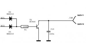
A question about the anti-ploc circuit from Jan-Peter.
Can I use one circuit to connect two or more UcD180 modules?
I'll have two cases:
- 2 modules with a PSU per module.
- 3 modules sharing the same PSU.
The anti-ploc circuit ground is connected at the star ground.
Can I use one circuit to connect two or more UcD180 modules?
I'll have two cases:
- 2 modules with a PSU per module.
- 3 modules sharing the same PSU.
The anti-ploc circuit ground is connected at the star ground.
Attachments
stef1777 said:A question about the anti-ploc circuit from Jan-Peter.
Can I use one circuit to connect two or more UcD180 modules?
No problem. The on/off pin is only interested in yes/no, so it's not sensitive to noise.
(I had long been wondering why at Philips "pop noise" was consistently called "plop" until it dawned on me that that's what the dutch called it. So if Philips were french we'd have been speaking of "ploc". Anyhow, before long our japanese customers were calling it "puroppunoizu")
Bruno Putzeys said:
..... Anyhow, before long our japanese customers were calling it "puroppunoizu")
Which translates back to "plop noise" so maybe they got that word from the Dutch🙂 Like they have inherited many words from the Dutch. Like "otemba" which comes from the dutch "ontembaar" and stands in Japan for a woman who can not be tamed (or something like that). The Dutch speaking here will know what I mean.
Sorry for being off-topic
Gertjan
New in my desk, a 5 channels UcD180.

5 x UcD180
2134 op-amps and BG NX-HiQ caps
3 PSU (one for 3 channels, one for each front channels)
MBR10100
BHC ALC10S
XLR at input with -12dB switchs for front channels
CC protection circuits with relays at output
WBT and Speakon connectors
4 fuses and 12V PSU for CC circuit and other use.
6 LEDS on front
2U cabinets
15kg
Close to be finished... but already working.
Thanks to Hypex, Schuro, Farnell, ITT, TI, BG, and HH.
Can you post a few more high res photos. Looks interesting
From the angle of this shot it's not apparent that you have enough speaker connections...? (Or input connections?)
Very neat though
Ed W
From the angle of this shot it's not apparent that you have enough speaker connections...? (Or input connections?)
Very neat though
Ed W
The box is from HIFI2000.
http://www.hifi2000.it/default.asp?id=9&mnu=9
More picture here :
http://www.homecinema-fr.com/forum/...&start=75&postdays=0&postorder=asc&highlight=
Sorry in French.
http://www.hifi2000.it/default.asp?id=9&mnu=9
More picture here :
http://www.homecinema-fr.com/forum/...&start=75&postdays=0&postorder=asc&highlight=
Sorry in French.
stef1777 said:New in my desk, a 5 channels UcD180.
5 x UcD180
2134 op-amps and BG NX-HiQ caps
3 PSU (one for 3 channels, one for each front channels)
MBR10100
BHC ALC10S
XLR at input with -12dB switchs for front channels
CC protection circuits with relays at output
WBT and Speakon connectors
4 fuses and 12V PSU for CC circuit and other use.
6 LEDS on front
2U cabinets
15kg
Close to be finished... but already working.
Thanks to Hypex, Schuro, Farnell, ITT, TI, BG, and HH.
Amazing that you can squeeze that all in that case. Would you do it again or would you use a bigger case if you knew before hand that it would be so tight?
Best regards
Gertjan
ghemink said:
Amazing that you can squeeze that all in that case. Would you do it again or would you use a bigger case if you knew before hand that it would be so tight?
Best regards
Gertjan
I'll definitively use the same small box. I was looking to build something very small. The challenge was there.
I need some help.
I'm trying to have the CC protection circuit working with the UcD modules.
The CC protection circuit is based on this circuit but modified to be used with 5 channels. All circuit fit on one board attached to the speaker connectors. The circuit is powered by a external and dedicated 12V PSU.
The CC circuit do not work with the UcD. It seems that the UcD have a -22V between the GND and the + speaker output when nothing is connected to the speaker output. The CC circuit do not like this as well.
I don't really know what is exactly this -22V. As well, the CC circuit and the module works well separately, and the -22V is like a "ghost" as the speaker do not burnt!!!
Any advise?
I'm trying to have the CC protection circuit working with the UcD modules.
The CC protection circuit is based on this circuit but modified to be used with 5 channels. All circuit fit on one board attached to the speaker connectors. The circuit is powered by a external and dedicated 12V PSU.
An externally hosted image should be here but it was not working when we last tested it.
The CC circuit do not work with the UcD. It seems that the UcD have a -22V between the GND and the + speaker output when nothing is connected to the speaker output. The CC circuit do not like this as well.
I don't really know what is exactly this -22V. As well, the CC circuit and the module works well separately, and the -22V is like a "ghost" as the speaker do not burnt!!!
Any advise?
Stef177:
Try to put a 100 Ohm (or so) resistor over each speaker terminal. This should kill the DC from the UcD modules...
Koldby
Try to put a 100 Ohm (or so) resistor over each speaker terminal. This should kill the DC from the UcD modules...
Koldby
koldby said:Stef177:
Try to put a 100 Ohm (or so) resistor over each speaker terminal. This should kill the DC from the UcD modules...
Koldby
It seems that I definitively have a problem with the modules (UcD180 v2). All five have the same problem.
If I try one module + PSU + power transformer. Mute directly connected on the GND connector of the module. Input shorted. Speakers output charged with a 100 Ohms resistor. I got -180mV. Without the resistor (open circuit), I got -20.6V.
Not lucky this time.
May be Bruno or Jan-Peter will have an idea of the problem.
Steff,
Because of the internal boost trap circuit to drive the positive fet you have an output voltage of 12VDC when the amp is OFF and without a load. You can remove this high impedance DC voltage when you connect a 47k resistor from the output to -V.
Or the best way would be to use a 12V zener and 33k from the output to -V. The kathode of the zener should go to the output of the amp, anode to the resistors and other side of the resistor to -V.
Regards,
Jan-Peter
- Home
- Amplifiers
- Class D
- UCD180 questions