hello Whortless
good job1 i like it)
but same question to you..
do U synchronized all your drivers IRS???
how u do it, if yes (sorry for my english)
Hi Kvazi13,
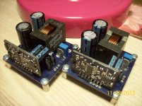
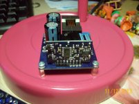
I am so sorry to answer very late. I can do this but i did not actually. There is a way to synch. them from input via an external osc. and my all amps has synch inputs which are disconnected now. Instead i used 47nf caps between the outputs for each R+L channels to synch. However, it does not look very necessary. All the amps running at nearly same frequency 387-390kHz without synching. I just finished the auxiliary PS for input opamps (OPA1632)+ comparator (LM311) and output relay protection boards which are ordered from seed studio.
I will add some photos soon.
Best wishes,
FH
Member
Joined 2009
Paid Member
Can anybody post the schematic and pcb for Bender's amp - none of the links work anymore and since he was willing to share I don't see any harm - or PM me if not to be posted ?


Req: CakeAmp v3 Schematic!
Thanks!
Was v3 ever published? If yes, is there any circuit change in v3 or was it just with added protection for OV and UV?
Thanks in advance!!
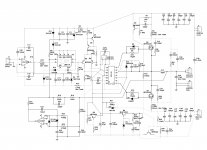
Is this what you're looking for?
Thanks!
Was v3 ever published? If yes, is there any circuit change in v3 or was it just with added protection for OV and UV?
Thanks in advance!!
Hello
greetings can any one advice me on how to design pcb for this schematic
single sided or double sided
warm regards
andrew😉
Hi Andrew
Looks like an old design. Why go with IR2110, needing level shifter on the input and over current protection seperately ... go with a IRS20957 .... maybe even the cake amp in 3 posts earlier ...
But to your question ... yes go for 2 sided and smd components
BR Baldin 🙂
UcD like topology
I find this design so much better than the 25W to 1200W design.
This has less component count, a much better driver with OC protection and dead-time setting.
I wonder why the other got so much attention.
This one would be good to try as both half bridge and full bridge.
Is this what you're looking for?
I find this design so much better than the 25W to 1200W design.
This has less component count, a much better driver with OC protection and dead-time setting.
I wonder why the other got so much attention.
This one would be good to try as both half bridge and full bridge.
I find this design so much better than the 25W to 1200W design.
This has less component count, a much better driver with OC protection and dead-time setting.
I wonder why the other got so much attention.
This one would be good to try as both half bridge and full bridge.
Highly agree 🙂
No need to, it because ofI wonder why the other got so much attention.
Code:
1200WBad
This design is bad, although they put a dedicated circuit to eliminate the offset, and balanced input, does not stop making noise, is a random design ........
Hello
greetings can any one advice me on how to design pcb for this schematic
single sided or double sided
warm regards
andrew😉
This design is bad, although they put a dedicated circuit to eliminate the offset, and balanced input, does not stop making noise, is a random design ........
- Status
- Not open for further replies.
- Home
- Amplifiers
- Class D
- UcD like topology amp.