Hi
Would you remake one with standard fets? Coz those that you used, would need to be ordered, if I even could... But for low power you can use many fets that are pretty old nowdays, but work great
Yet again, outstanding work, since you can put TLs in instead of ADs
Would you remake one with standard fets? Coz those that you used, would need to be ordered, if I even could... But for low power you can use many fets that are pretty old nowdays, but work great
Yet again, outstanding work, since you can put TLs in instead of ADs
of course it could be replaced with -some- nice opamps for buffers...
and it has been discussed on and off this forum a few years(3?) ago..I think your aware of that 😉
the ussual buffers in the menu was NE5532 and the "AD"s ....but nowadays, there are many -much better- opamps out there to use...
and it has been discussed on and off this forum a few years(3?) ago..I think your aware of that 😉
the ussual buffers in the menu was NE5532 and the "AD"s ....but nowadays, there are many -much better- opamps out there to use...
Thank you
Well, it isn't anything out of the ordinary or unusual - but it's exactly what I was looking for - except that I've already built them.
But thanks anyway. 🙂
Well, it isn't anything out of the ordinary or unusual - but it's exactly what I was looking for - except that I've already built them.
But thanks anyway. 🙂
Very nice
Dear Bender,
very nice. Excatly, what i was looking for. And the documentations is perfect.
Do you think, i can replace the output coil by a ring-core? Any negative impact to fear?
Is the power limited by the Mosfets only? Can i get more power by bigger Mosfets, Caps and Coil?
Thanks
Dear Bender,
very nice. Excatly, what i was looking for. And the documentations is perfect.
Do you think, i can replace the output coil by a ring-core? Any negative impact to fear?
Is the power limited by the Mosfets only? Can i get more power by bigger Mosfets, Caps and Coil?
Thanks
Hi iwan_audio.
Using PS with 40-45V per rail you can obtain 200W @ 4Ohm using irfi42112 or irfi4019, there is no need in other changes (maybe reset OCP thresholds) and don't forget about proper heatsink 🙂. It's also possible to replace output inductor by ring core choke, you can find all necessary information in this forum.
Using PS with 40-45V per rail you can obtain 200W @ 4Ohm using irfi42112 or irfi4019, there is no need in other changes (maybe reset OCP thresholds) and don't forget about proper heatsink 🙂. It's also possible to replace output inductor by ring core choke, you can find all necessary information in this forum.
Very nice work, Bender.ru!
I have a question, why is R21 referred to GND and not to
COM, as shown in the datasheet from IRF?
I have a question, why is R21 referred to GND and not to
COM, as shown in the datasheet from IRF?
hmm, let's think together 🙂. What is going on if you connect R21 at drivers COM pin?
R21+VD5 act as power supply for low side driver.
R21+VD5 act as power supply for low side driver.
Nice work Bender.ru
I will build a similar concept with IRS20955. Your schematic is
good input.
@Kay
If you connect R21 to Com you will have charging current for C12 and therefore no voltage at VCC.
Current through R21 can be calculated very easy
(40V-VD5)/R21=(40V-15V)/1500Ohm=16,6mA
Power loss in R21 Pv=416mW. So 500mW resistor is o.K.
thanks Bender.ru + Eljo
but in the datasheet we find a two resistors providing
"DT", one to VCC and one to the negative rail.
You fix DT to "DT1"? (Table1, page 15 on datasheet)
If I'm not completly stupid now, why do you do this?
If I use other Fets, I must change this?
@Eljo
please post your design too
of courseR21+VD5 act as power supply for low side driver
but in the datasheet we find a two resistors providing
"DT", one to VCC and one to the negative rail.
You fix DT to "DT1"? (Table1, page 15 on datasheet)
If I'm not completly stupid now, why do you do this?
If I use other Fets, I must change this?
@Eljo
please post your design too
Hi RX5,
Sorry to side track. Ucd recently caught my interest, after being absent in the diy field for a long time I need to do lots of catching up!
I came across the thread you have started (my 1st D-amp working) years back and again got caught by your enthusiasm that make me even more interested! Now I’m planning to build my own ucd based from your circuit diagram after your mods (hope you won’t mind!) unfortunately your attached circuit diagrams and photos are no longer available for viewing. If you still have the copy of the circuit diagram, pls be so kind to post here or send me by email, some details for troubleshooting as understand were clearly mentioned from the thread. Thanks!
-mannycc
Did anybody do a pcb design from bender's schematics in Eagle from CADsoft?
I am working on one, but if someone allready did it I can save myself the trouble 🙂
I am working on one, but if someone allready did it I can save myself the trouble 🙂
 .
.
Re: ^^^^
especially the "octopus style" wired IC!😀
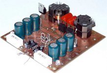
Workhorse said:Very beautifull pcb......!!!!
especially the "octopus style" wired IC!😀
Bender, i am just finished your amp for sub. Its produce powerfull, perfect quality bass with very low loss and distrotion . The PCB ideal for sub use!!!
-----------------
Best regards, Denis
-----------------
Best regards, Denis
- Status
- Not open for further replies.
- Home
- Amplifiers
- Class D
- UcD like topology amp.