Hi everyone
I'm a newbie on the ClassD
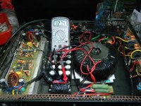
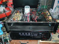
My ClassD two channels
Channel A normal
Channel B is hot Zobel resistor 10ohm
I debug, but can not find
Can someone help me
Thanks a lot
Figure below my ClassD
I'm a newbie on the ClassD
My ClassD two channels
Channel A normal
Channel B is hot Zobel resistor 10ohm
I debug, but can not find
Can someone help me
Thanks a lot
Figure below my ClassD
An externally hosted image should be here but it was not working when we last tested it.
An externally hosted image should be here but it was not working when we last tested it.
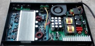
I assume that after inserting the missing chips into the empty sockets of channel A its snubber resistor will go hot as well.
that is my schematic.
It works very well but you've to tune the circuit with real components.
I prefer the IRS20957 version because there are less components, more protection and best performance.
Hello pergo,
I simulated your schematics in LTSpice and I found that there are big current spikes through the output MOSFETs, up to 80A.
This seems to be due to simultaneous conduction through the 2 MOSFETs.
Does this happen in practice or is it a simulation artifact ?
Hi,
IR2110 has a concept-behaviour model, so it's good for test "does it work?", but not good for real performance.
It helps a lot, but real circuit (or breadboarding) is the right way to proceed and tweak.
IR2110 has a concept-behaviour model, so it's good for test "does it work?", but not good for real performance.
It helps a lot, but real circuit (or breadboarding) is the right way to proceed and tweak.
The IR2110 , as other models , has a realistic behaviour in simulation.IR2110 has a concept-behaviour model, so it's good for test "does it work?"
The con in simulation is that you cannot consider all the mounting parasitic parameters.
This seems to be due to simultaneous conduction through the 2 MOSFETs.
Does this happen in practice or is it a simulation artifact ?
If its a shotthrough , adjust the deadtime. Also it maybe caused by the output capasitance of the mosfets. Have you snubbers on them?
The IR2011 is not a trusted model.
As you can see opening the model, there's the answer by analog@ieee.org
IR2011 is more then some voltage controlled switches, triggers and diodes.
This model works well but is not the Saint Graal.
As you can see opening the model, there's the answer by analog@ieee.org
An externally hosted image should be here but it was not working when we last tested it.
IR2011 is more then some voltage controlled switches, triggers and diodes.
This model works well but is not the Saint Graal.
Hi,
Why? and what you mean by real performance?
Regards
MANOJ
so it's good for test "does it work?", but not good for real performance.
Why? and what you mean by real performance?
Regards
MANOJ
MY DIY TORRIDAL 90 0 90 AC
Hi andrew,
for 127V supply which MOSFET you are using??
Peak RMS is 2016W @8R load current 16A
Good design
Regards
MANOJ
Hi NMOS, is this D-amp base on IR2110 ? Carrier base or self OSC. It look's new to me.Hope you can give us an idea.
Hi Andrew,
for +/-125 V rail we can use FDA59N30 MOSFET without totem pole
Peak out put 1950 W@8R max @16A and 3900 W @4R max @31A current, DT with 50nS
Regards
MANOJ
very high Qg !!!!!greetings mosfet used is IXFN80N50Q2
for +/-125 V rail we can use FDA59N30 MOSFET without totem pole
Peak out put 1950 W@8R max @16A and 3900 W @4R max @31A current, DT with 50nS
Regards
MANOJ
Hi NMOS, is this D-amp base on IR2110 ? Carrier base or self OSC. It look's new to me.Hope you can give us an idea.
Yes its self OSC, my latest design ready to start promote and sell in qty
850 W @ 8 OHM RMS
- Home
- Amplifiers
- Class D
- UCD 25 watts to 1200 watts using 2 mosfets