The problem with the startup in selfoscillating class d amp usually is that it MUST start with the negative impulse at the output, to let the bootstrap capacitor charge (I mean the bootstrap capacitor of the mosfet driver). If this condition is not met (if the comparator waits for INITIAL positive impulse at the output), then the bootstrap capacitor is not charged yet, and it is not possible to open the high side mosfet and it is not possible to generate any positive voltage at the amp output. So the amp simply will not start to oscillate...
To solve this problem, it is usually enough to connect amp output to the positive voltage rail using 50K-100K resistor. This will generate small positive voltage offset at the amp output after power is on, and the input comparator will initiate the negative cycle first, which will charge driver's bootstrap capacitor effectively...
Hi 81bas
Good point, don´t know why I have not remembered this from some of the early designs of UcD, where this kind of resistor was included 😱
But I think it woould be more effecient going to the negative rail (the resistor that is 😉), as this will create a charging path no matter the "direction" of the first pulses. ..... but very god point 😉
Have been playing with the feedback values to get a higher gain (first walues gives some 10 times ..... 😀 )
But bread board and class-d is not good for performance .... which should be evident ... so raising the gain also raises the noise a lot.
This once again makes me wonder whether single sided board, and through hole components can actually be made to work sufficiently well for any measure, and whethe it is worth the effort.
Tekko good work ... and congratulatios again 🙂
Tekko, how is the noise leve of your amp, honestly, and compared to an ok commercial AB amp as an example??
Tekko could you post some more scope pictures?
- 1kHz half output or so
- Switching before the filter
- input to IR2110 ligh and low
There is a slight hiss, kindof like when an amp it turned to max volume with nothing connected to the inputs.
At startup it farts a few times.
1V is not enough to bring it up to clipping. And im not using IR2110, im using IR2010. I have no deadtime except for 22ohm gate resistors and !n4148's in parallel for instant gate discharge, heatsink stays nice and cool on 2x 15V input.
I'll take some scope shots once i find my dummy load.
81bas, I have now tried the little trick of a resistor on the output .... must say that connected to the positive rail works, and connected to the negetive, does not produce any improvements! ..... have to think a bit more about this 😉
But still it is not enough to make it start everytime with the big cap in the feedback loop .... guess it does need the DC gain, when strating up .... this is bummer for when it works (with the cap) there is virtually no DC offset on the output ..... so how to make this work, and eliminate other offset reducing things 😕
But still it is not enough to make it start everytime with the big cap in the feedback loop .... guess it does need the DC gain, when strating up .... this is bummer for when it works (with the cap) there is virtually no DC offset on the output ..... so how to make this work, and eliminate other offset reducing things 😕
I modified the circuit alittle by adding a phase lead network like in the putzeys article.
scope shots.
Output from mosfets:

1kHz full volume, those artifacts were the function generator software acting up:

And finally 20kHz, its fuzzy because i forgot to turn down the volume on a video stream, but the effect of low switching frequency is clearly visible here:

After a minute of that the amp reeked of burnt transistor package, something got hot at 20kHz but it wasent the heatsink. For what it is, it sounds incredibly good. 🙂
scope shots.
Output from mosfets:
1kHz full volume, those artifacts were the function generator software acting up:
And finally 20kHz, its fuzzy because i forgot to turn down the volume on a video stream, but the effect of low switching frequency is clearly visible here:
After a minute of that the amp reeked of burnt transistor package, something got hot at 20kHz but it wasent the heatsink. For what it is, it sounds incredibly good. 🙂
Last edited:
Now im using HUF75337's instead of IRF540 after a short on the output caused the high side fet to go belly up.
I also stuck a 1nF cap in the audio input, that seem to have improved the sonics alittle.
I also stuck a 1nF cap in the audio input, that seem to have improved the sonics alittle.
hi carlos what aplication do u use for IRS2092? what schematic i have somthing like this but i do not know if it works
I've seen the IRS2092 and i may get some of those sometime in the future.
Anyways i've removed all of the hiss, now its only the noise from the computer soundcard that manifests itself as a faint hiss, with the computer turned off, the amp is dead silent. How ?
I put a 1nF cap on the audio input. The switching frequency is now at 6µS.
Anyways i've removed all of the hiss, now its only the noise from the computer soundcard that manifests itself as a faint hiss, with the computer turned off, the amp is dead silent. How ?
I put a 1nF cap on the audio input. The switching frequency is now at 6µS.
1µF is too much for fullrange audio, not only does it supress the upper audio range, it also imposes a greater phase shift.
does it supress the upper audio range
No, it doesn't. Actually it rises up the voltage around 20 kHz!
it also imposes a greater phase shift
...in open loop. Wich is unimportant, since we are talking about an UCD amplifier.
But the higher attenuation of switching freq makes more loop gain, wich decreases the distortions.
In simulatuion, a bigger cap also lowers the switching frequency.
I use a 20µH inductor and a 470nF cap.
I use a 20µH inductor and a 470nF cap.
I just made a littlre discovery, i had accedently used a 1N4007 for the bootstrap supply, no wonder that part of the board was getting hotter than hell.
Put in a UF160 in its place and its still getting hot but not as hot as before.
Put in a UF160 in its place and its still getting hot but not as hot as before.
The amp is now off the 2x15v regulated psu. Currently it runs off a 2x12vac transformer and its way cleaner now than it was on the stabilized psu. Despite no stabilization of nthe rails, there is no hup and the amp starts silently with a very faint "tot" noise.
Heres a shot of the carrier resudial:

And did i mention theres no heating what so ever of the mosfets, only the gate driver get alittle hot but i guess that is normal.
And sound quality ? BRILLIANT!!😀😀
Heres a shot of the carrier resudial:
And did i mention theres no heating what so ever of the mosfets, only the gate driver get alittle hot but i guess that is normal.
And sound quality ? BRILLIANT!!😀😀
2x 15v is low voltage for anything to heat up, I had my on 2x60v and no heatsink, getting warm only... it really depends on fets and all
The gate drive is fed from a separate 15V psu. With the regulated 2x 15V psu i got ringing and switching noise, with the 2x18V non regulated its squeeky clean.
Olá,
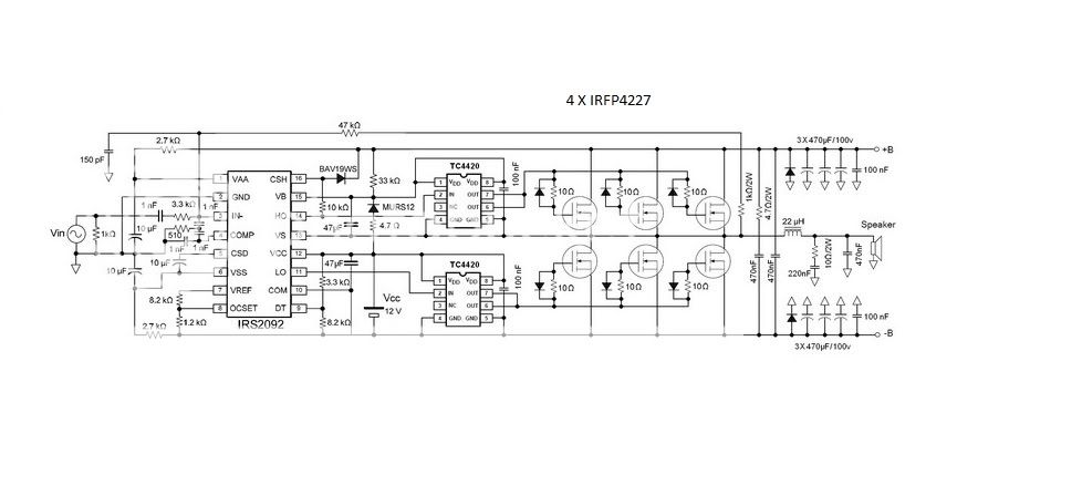
I take the aplication note and reference design at www.irf.com
The IRS2092 is full of security systems.
There is a need to heed well this protection system to develop a design that works well.
I suffered a lot but I got a spectacular result.
I can help in every possible doubt.
Bye
Captain Carlos
I take the aplication note and reference design at www.irf.com
The IRS2092 is full of security systems.
There is a need to heed well this protection system to develop a design that works well.
I suffered a lot but I got a spectacular result.
I can help in every possible doubt.
Bye
Captain Carlos
Attachments
- Home
- Amplifiers
- Class D
- UCD 25 watts to 1200 watts using 2 mosfets