It's by far not as bad as you imagine. And his imagination tells a lot about how things are going in life for somebody...
The protection that tripped was in the power supply and involves a current sense transformer with 200 turns and inherent antenna properties. Ironically, this transformer is working at mains frequency, it's a linear circuit involving op-amps and a PIC. It's calling for a couple of ferrite beads and caps to avoid rectification of ambient RF in the input LTP of a bipolar op-amp.
Protection against wrong oscillation modes is very useful as the product ages. Imagine the result of an open feedback resistor or a cold joint somewhere. Bang! or immediate shutdown.
btw: No, it does not make funny noises unless the phone is placed crazy close to the modulator 😀
btw2: That's without an enclosure, bare pcbs on a wood bench 😉
Last edited:
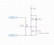
Today i built a little circuit that provides a delayed turnon to let the caps charge before the amp goes active.
Heres a short vid of the cir in action:
YouTube - Delayed turnon circuit
Heres a short vid of the cir in action:
YouTube - Delayed turnon circuit
Today i built a little circuit that provides a delayed turnon to let the caps charge before the amp goes active.
Heres a short vid of the cir in action:
YouTube - Delayed turnon circuit
can you provide schematic for delay turn on ?

It have turned out im still below 200kHz, had moved a knob on the scope without knowing it, so that it looked like the frequency had increased to 300kHz.
And now i noticed there were too many resistors in the input part so when i removed those i actually did climb to 250kHz, and it sounds like it improved ther sonics as well.
And now i noticed there were too many resistors in the input part so when i removed those i actually did climb to 250kHz, and it sounds like it improved ther sonics as well.
Last edited:
Hi tekko,
I'm curious to know ... tr1 puts down pin SD IR210? If so, there was no need to use transformer IC + bjet +parts🙂
I'm curious to know ... tr1 puts down pin SD IR210? If so, there was no need to use transformer IC + bjet +parts🙂
AP2, i used the enable/disable in the current source like in the philips ucd schematic: http://www.nxp.com/documents/user_manual/UM10155.pdf
pad 3 and 4 in my schematic, tho i guess using the sd pin on the IR2010 would yield similar results, i chose what i chose because i dident feel like digging up the ground plane around the SD pin.

And here are two new pics of the updated startup delay:
Amp in standby, no oscillation:

Amp active:

The white led was supposed to be yellow, picked the wrong bag.😱
pad 3 and 4 in my schematic, tho i guess using the sd pin on the IR2010 would yield similar results, i chose what i chose because i dident feel like digging up the ground plane around the SD pin.
And here are two new pics of the updated startup delay:
Amp in standby, no oscillation:
Amp active:
The white led was supposed to be yellow, picked the wrong bag.😱
well i use not only a delayed poweron but a more or less instant power off rather than having it keep oscillating as the psu drains out with a pop of squeek as the end result.
It's similar to this layout:

And its rock solid, the carrier resudial is so clean that one could think it was the output of a function generator, not even the slightest hint of switching noise.
Are there eagle or gerber files to DL for this board?
Yes but that is an old design which have been superseeded by a much better performing version.
I will publish the latest design sometime this weekend.
I will publish the latest design sometime this weekend.
Now i have killed back the 300mV dc offset on the output down to -3mV by adding approx 870kOhm between one input and the negative dc rail.
This also aids startup.
This also aids startup.
AP2, i used the enable/disable in the current source like in the philips ucd schematic: http://www.nxp.com/documents/user_manual/UM10155.pdf
pad 3 and 4 in my schematic, tho i guess using the sd pin on the IR2010 would yield similar results, i chose what i chose because i dident feel like digging up the ground plane around the SD pin.
And here are two new pics of the updated startup delay:
Amp in standby, no oscillation:
Amp active:
The white led was supposed to be yellow, picked the wrong bag.😱
Hi Tekko,
I did not completely read the posts but try these;
i) put an electrolitic cap parallel to R6 for delayed turn on, also disconnecting R2 from gnd can be used as disable function.
ii)Or put an electrolytic cap from vdd to SD pin of IR2112 and let the SD pin go to -24v with a resistor. For both i&ii you need to make some calculation for cap and/or resistor values.
iii)To adjust the offset use offset balance fuction already supplied on LM311 (pins 5,6).
Regards
FH


Hello Tekko ,
did sound quality improve?
from what do you feed the signal to the amp? differential output source, or plain Cd player?
Regards,
savu
did sound quality improve?
from what do you feed the signal to the amp? differential output source, or plain Cd player?
Regards,
savu
The audio source is my computer, i mix the channels into mono, then run the mono signal through two opamps, one inverting and the other non inverting.
After that the balanced signal travels thround an old ethernet cable to the amp, around 7 meters worth, at the amp its received by the buffer that i chose to have an input impedance of 18kohm.
There might be a slight improvement in audio quality.
After that the balanced signal travels thround an old ethernet cable to the amp, around 7 meters worth, at the amp its received by the buffer that i chose to have an input impedance of 18kohm.
There might be a slight improvement in audio quality.
balanced lines are great .. you can expand even further than 7 meters ...
try to use shielded Ethernet cable.. or even better shielded microphone cable to be on the safe side with parasitic pick-up.
regards,
savu
try to use shielded Ethernet cable.. or even better shielded microphone cable to be on the safe side with parasitic pick-up.
regards,
savu
- Home
- Amplifiers
- Class D
- UCD 25 watts to 1200 watts using 2 mosfets