Hi All
Remember one thing if you connect more than 50V supply rail you should provide speaker delayed on circuit.Min 3Sec. delay
Regards
Manoj T.M
Remember one thing if you connect more than 50V supply rail you should provide speaker delayed on circuit.Min 3Sec. delay
Regards
Manoj T.M
manojtm:
Huge distances between mosfets and driver .🙁 .Also ir2110 can not drive more than one pair,for more you need tc4420 to help.Put mosfets close together.
Also you have no decoupling,to much copper for whitching bus=>huge emi.Resistor sensing for short only in neg supply is not a good ideea,it may not save amplifier with short to rails when upper mosfet is on.
I posted a pop free start and stop level shifter modification a while ago..use it..😀..speaker conection delay is needed anyway because the amplifier will not always start to oscillate with load.Also 1 kohm dummy load and 10kohm startup resistors are needed.
Dimonis:
clipping occurs no matter what input you use at low supply.
andrewlebon:
For 2 ohm and 1 ohm load you also need to modify output inductor and capacitor,also you need 50 A rated power transistors .
Last edited:
Also manojtm you have a huge ground loop around the entire board..do not make it like this ..it is not very good...
Dimonis:
clipping occurs no matter what input you use at low supply.
.
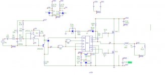
So you want to say I'd get clipping on the below schem ?
GAIN=1 , supply +-5V , input = 40V rms
And NO clipping!
Attachments
Yes you are right,my mistake...🙂i was thinking at something else😀..in this configuration there will be only power stage clipping at 40 volt rms sinusoidal....
Last edited:
That's why i prefer the inverting type , and it's more stable.
Almost every amp might be done the similar way.
Recommend to all.
Almost every amp might be done the similar way.
Recommend to all.
Last edited:
Hi CPX
I think MOSFET will not take more current,you can use any number of MOSFET in parallel.Only thing is gate capacitance. If you are using BJT(Bipolar Junction Transistor) your point is right.
Class D is not New For Me. 3 year back I completed one;still it working ( used 2x IRF240 and 85V Supply)
I think MOSFET will not take more current,you can use any number of MOSFET in parallel.Only thing is gate capacitance. If you are using BJT(Bipolar Junction Transistor) your point is right.
Class D is not New For Me. 3 year back I completed one;still it working ( used 2x IRF240 and 85V Supply)
Hi CPX
My older PCB design(working one) I used large GND Plane, it give very noisy and i cut the plane in middle point then i connect one thicker 2mm Sq. wire from the center of the BUS capacitor (10,000uF/100V) so my side large GND ie. is near by 1st. coil is not good.
My older PCB design(working one) I used large GND Plane, it give very noisy and i cut the plane in middle point then i connect one thicker 2mm Sq. wire from the center of the BUS capacitor (10,000uF/100V) so my side large GND ie. is near by 1st. coil is not good.
Hi don2007ksa,
i posted the new schematic a while ago!!!!!!!!!!!!!!
pls not everyone, In class d amp use ALC without ALC in low freq. Bus pumping will occur( some blasting sound will produce and your spk will damage).
for ALC use BA6110
i posted the new schematic a while ago!!!!!!!!!!!!!!
pls not everyone, In class d amp use ALC without ALC in low freq. Bus pumping will occur( some blasting sound will produce and your spk will damage).
for ALC use BA6110
manojtm :
irfb4227 has 46A and 200 volt rating..you can use 2 of them...but ir2110 can not drive more than one Qg~100nC pair mosfets.irf240 is a low current easy driven Qg<40nC mosfet..that is why it works for you...
When designing switching electronics pcb you mush have VERY SHORT TRACES and lots and lots of ground😀(ground plane on one side).
Look at the original board an this thread..is very good
I do not understand why you need an alc chip..you should use a subsonic filter..but i am using a current level limiter .
Last edited:
Hi CPX,
IR2110 can handle 2A Current
you are correct RF side must have very short traces and GND plane
My older design OSC = 125KHz and used long traces 1mm thick; No problem found
IR2110 can handle 2A Current
you are correct RF side must have very short traces and GND plane
My older design OSC = 125KHz and used long traces 1mm thick; No problem found
Yes 2A is enough for 100nC and 4500pF but no more...
125 khz is a very low of., anyway you can not say "no problems found" without making THD and IMD tests at high current😀...music is not a valid testing method

125 khz is a very low of., anyway you can not say "no problems found" without making THD and IMD tests at high current😀...music is not a valid testing method
Yes 2A is enough for 100nC and 4500pF but no more...
I agree and not , depends on frequency , at about 300kHz your figures are right , but the 2110 will be hot 😡 , if freq lower it can drive more , proportional.
Last edited:
damn, this thread hot again, anyone willing to sacrifices mosfet or ir2110 and do experimenting in real life until success follow by simulation first. one thing i take note from iraudamp9 desing, they use bjt buffer to parallel the mosfet with irs2092, this cannot be applied to ir2110?
dimonis:
Yes..i am thinking 300khz...anything lower than 250 khz and the audio band gets too narrow for my taste.
norazmi:
Bjt buffer is feasible with ir2110 but the switching may not be so clean,i prefer dedicated driver, but for my needs(max 500W) one pair of mosfets in enouth.
Yes..i am thinking 300khz...anything lower than 250 khz and the audio band gets too narrow for my taste.
norazmi:
Bjt buffer is feasible with ir2110 but the switching may not be so clean,i prefer dedicated driver, but for my needs(max 500W) one pair of mosfets in enouth.
500w into 8 ohm? its loud enouh and will vibrate ur house hard hehehe.. 300Khz... hmmm i`ve tried before increase freq at approx 500 Khz, mosfet survive and run with cool condition, but the only one hot is filter caps 1uf, huh.... so im worried it will explode if play long, so i reduce it back to 250 khz, why that caps hot?
opsss, one more, CPX but in simulation i did parallel 2 pair irf250N , what i can see is mosfet will be more cool and thd is good than 1 pair and it will double the current at output, idk its not clean or not, because its only simulation, but my experience with LTspice it can be trusted st lest +/- 10% accuracy. Imma on the way will do parallel the mosfet with discrete ucd and will report how good they will, let see after i`m back from vacation.
norazmi:
My amplifier will deliver maximum 20A in 1.25 ohm load..so maximum 500 W at 1 khz..it will deliver a little more at 20 hz and much less at 16 kz(around 16A).As i said before i only have +-48 volt suplies.
For eficiency is better to paralel mosfets yes...but that increases complexity and is hard to keep THD low.It is better to use only 2 modern mosfets(irfp4227) than 6 older ones(irf240), but if you want very high continuous rms currents(25A-100A) you will have to use more mosfets to obtain it.
If you make experiments at high currents please post THD and IMD..the "i can hear music so it works" testing is not very convincing for me🙁.
Spice is very good but the result will only be real if you add to the simulation all parasitic factors in your real implrementation,and this is very hard to do...
Have a pleasant vacation!
Last edited:
dimonis:
Yes..i am thinking 300khz...anything lower than 250 khz and the audio band gets too narrow for my taste.

But the people here require kiloWatts , 🙄, so the audio band don't mean much to them , only power!😱
- Home
- Amplifiers
- Class D
- UCD 25 watts to 1200 watts using 2 mosfets