Schematics ??
hi all I have doubts why diagrams removed
if all this, now this amplifier with sigma delta modulator is basically the work of international rectifier IRAUD1 and pag.IRF is available in this forum is to discuss and learn and then teach because it removed the schematics and PCB artwork? ?
greetings to all ...if the moderator permits desire iraud1 put the diagram and leave here as a reference in fact heard super good
Attachments
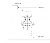
Was ist ein OTA? (Dynamiklimiter mit OTA LM13700, LM13600, CA3080, transconductance-amplifier, agc-amplifier)
link to EXFLACO schematic Triell limiter
link to EXFLACO schematic Triell limiter
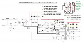
one more smps completed
warm regards
andrew lebon
hi andrew
do ee16 or 19 have gap in the middle legs.pc cores have gap in midde legs i got cores without gap too.
did you use 15swg single solid wire or srands.
i have 23 swg wire thinking of paralling 5 in primary is it ok.
regards
thanks
Attachments
Hi Ravs
greetings EE19 core use one with gap and use 5 parallel strands 23 swg
warm regards
andrew lebon
greetings EE19 core use one with gap and use 5 parallel strands 23 swg
warm regards
andrew lebon
Attachments
![DSCN4250 [320x200].JPG](/community/data/attachments/318/318058-ec75790004aa73d0d8b35345fe317716.jpg?hash=7HV5AASqc9)
Last edited:
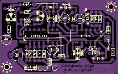
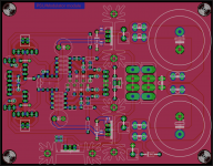
I've cobbled together a PSU/modulator board to go along with the power module boards.
It may not look too impressive but the seemingly long traces only handle TTL DC signals (enable/mute) so it shouldent be an issue.
This module uses a LM393 and is thus designed to be used with two power modules to form a full stereo amplifier, however i am not sure this will work as the two halves of the LM393 may interfer with each other, causing problems such as noise.
Attachments
I'm trying something with this topology, adding a integrator sensing the negative input and providing a signal to the positive input based on the error between the input signal and feedback signal, kinda like Anaview/Abletec do in their amps. This supposedly lowers/minimizes linear distortion or something like that.
The basic circuit: http://i.imgur.com/40lVqnK.png
The basic circuit: http://i.imgur.com/40lVqnK.png
Hi Insomnia,
yes with gate resistor 6.8 ohm
Regards
MANOJ
have problem, your amp not working.
1. 74HC04 IC will be very hot and bulb from negative rail is lighting, after remove 74HC04 IC Bulb is off but then IC2110 will be hot quick.
2. If remove IR2110 bulb from negative rail is lighting too
3. If remove 74HC04 IC bulb is off
Bias - ..... I have connect with negative rail from power supply - 75V DC
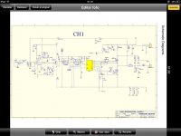
Is it possibile wiring 74HC04 IC from audamp 3.0 is wrong in your schematic ?
Attachments
Last edited:
Hi Insomnia,
AUD600 schema is working one
BIAS PIN
PIN-3 connected to -75V rail { must be conected otherwise AMP will not work }
PIN-2 Over Current Signal { not required if you don't need OC }
PIN-1 +12V bias voltage with respect to -75V rail { must be conected otherwise AMP will not work }
Regards
MANOJ
AUD600 schema is working one
BIAS PIN
PIN-3 connected to -75V rail { must be conected otherwise AMP will not work }
PIN-2 Over Current Signal { not required if you don't need OC }
PIN-1 +12V bias voltage with respect to -75V rail { must be conected otherwise AMP will not work }
Regards
MANOJ
This circuit have now been built and tested: http://i.imgur.com/ny9dda6.png?1
On idle the thing is dead silent, if i press my ear against the teeters i can just barely make out a hiss/buzz and unlike the previous prototype, this one is also rock solid, no signs what so ever of unstability regardless of music type or volume.
A pic of the prototype itself: http://i.imgur.com/PtWeIia.jpg
finally thanks insomnia for posting the amp600 schema i have been searching long for it. 🙂 🙂
I also made my pcb following this schematic. Added protection and bias on same board.
Have you seen that.
thanks i have seen it
http://www.diyaudio.com/forums/class-d/226812-my-class-d-amp-29.html#post3484095
have you tested it?
http://www.diyaudio.com/forums/class-d/226812-my-class-d-amp-29.html#post3484095
have you tested it?
- Home
- Amplifiers
- Class D
- UCD 25 watts to 1200 watts using 2 mosfets