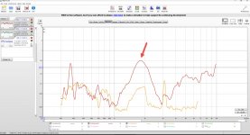
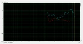
I think the distortion measurment I made with arta are not correct. The asio4all causes crackeling during the measurement. So I switched to REW which allows me to use different input and oupt devices without asio4all.
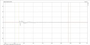
There is a distortion dip at about 1,8khz. Can this maybe caused by sharp box edges?
1,8khz wave length is about 19cm which could be the distance from tweeter diagraphm along the wall to end of the box.
There is a distortion dip at about 1,8khz. Can this maybe caused by sharp box edges?
1,8khz wave length is about 19cm which could be the distance from tweeter diagraphm along the wall to end of the box.
Attachments
Diffraction should not show up as a harmonic distortion peak (or dip- what you show is a peak).There is a distortion dip at about 1,8khz. Can this maybe caused by sharp box edges?
If you have not broken in the suspension by running low frequency tones near Xvar or "excercised" the cones by pushing them to that excursion by hand, I'd suggest doing that before more tests.
If the SPL reading of "83dB" in the test is calibrated, .5% distortion would be 45dB lower, only 38dB, which may be room or other noise. What distance are you testing at? What is the SPL capability of the test mic?
What does distortion look like when run at levels near predicted maximum excursion? "Bracketing" several runs of increasing level would give some idea of what is actually going on, what does distortion look like when run at levels near predicted maximum excursion?
Last edited:
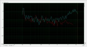
the distortion peak 🙂D english is not my native language) comes from the tweeter and not from the woofer. I have made distortion measurment of both seperatly and peak is coming from HF10AK. So I think break-in the woofers does not help. Maybe HF10AK also needs some break in. I have done the measurment directly in front of the horn moth (2cm) to avoid room relfections. The microphone is the Audix TM1 Plus which should be able to handle this. SPL was not calibrated. It was at low listening level. But I will do some further test tomorow.
The HF driver suspension should not need break-in.
The LF is dropping acoustically much steeper than the HF, no reason to have the HF cover more low end than it needs to.
Looks like you may be an using 18dB per octave crossover, if we are seeing excursion related distortion (unlikely at this low level) going to 24dB BW (and raising the Xover frequency, no reason both LF and HF need to be at the same) would decrease distortion.
Didn't realize it was a full range measurement- helps to show the measured response too, to see the differences. Hard to tell what the distortion might be with both drivers playing.
If you do individual checks, the unused drivers should be shorted out so they don't act as passive radiators.
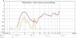
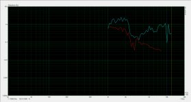
ok did some further tests today regarding this small distortion peak at 2khz. I took my second HF10AK (so I could also exclude the one in the horn has a problem) and measured frequency response (from 1khz and up) and distortion in free air with REW at about 13cm in front of the Compression driver exit.
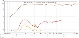
Then I put the microphone 13cm in front of the exit of the HF10AK in the horn (which is about 1-2cm in front of horn mouth). All other settings (volume, Crossover and EQ´s) where the same. EQ and Crossover was set now to 1,8khz and equalized to the horn-version but where the same for both measurements. The small peak is also there on the free air measurement, so it seems to come from the driver itself. But anyway it´s just a small peak so I don´t think I should worry about. The cool thing about the comparison was to see how much SPL the horn gives to the driver. At 2khz it´s more than 10db.
Then I put the microphone 13cm in front of the exit of the HF10AK in the horn (which is about 1-2cm in front of horn mouth). All other settings (volume, Crossover and EQ´s) where the same. EQ and Crossover was set now to 1,8khz and equalized to the horn-version but where the same for both measurements. The small peak is also there on the free air measurement, so it seems to come from the driver itself. But anyway it´s just a small peak so I don´t think I should worry about. The cool thing about the comparison was to see how much SPL the horn gives to the driver. At 2khz it´s more than 10db.
Attachments
Time Allign
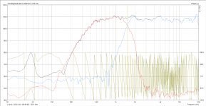
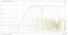
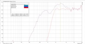
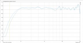
ok just playing around with some crossover filters in hypex filter design (fa503) between midrange and tweeter. Midrange already falling down very step with about 32-36db octave. I have added a LR4(24db) at 2000Hz to them which results in 48db acoustically at about ~1600Hz and also removes the small peaks above 2,5khz.
To Tweeter I assigned LR8(48db) at 1570Hz.
Both together results in an acoustic crossover at about 1600Hz with 48db octave (see measurements).
OK now the difficult question. How to time align them and match phase to each other? We have two different filters (LR4 on midrange and LR8 on tweeter) at two different electrical crossover frequencies (2000Hz and 1570Hz).
The first question for me. Do I have to delay the tweeter or the midrange? normally midrange is physically nearer to the listening position (delay midrange?) but I have heard the distance is longer because the sound is first going to the horn throat, getting reflected here and then runs through the horn to the listening position. If going this way I normally should delay the tweeter.
I have played around with delays and with a delay of the midrange at 203µs (69,7mm regarding hypex) I get the best summation at crossover frequency and the highest dip when inverting one driver.
But is this correct? How to do this correctly step by step?
In general. I have heard the LR8 will not sound as good as LR4 because of the multiple phase changes. Is this correct?
Problem is that the midrange is falling already very step by it´s own so I need to use those step filters.
Attachments
you could try this method:
Using REW to Determine Time Delays Between Drivers - Technical/Modifications - The Klipsch Audio Community
As long as you haven't added so much delay that you have an extra unnecessary wavelength it would seem like you have the correct delay if your getting a good null.
In terms of LR4 and LR8 sounding different I personally couldn't tell any difference crossing at 500Hz. You can plot the excess group delay of the finished speaker and see if it crosses audibility thresholds at any frequency if you are worried. One thing to keep in mind is that for excursion protection there is no need to use greater than LR4. Different filter orders will contribute a different delay at the crossover frequency so your LR8 on the tweeter adds more delay to the tweeter than the LR4 on the midrange.
originally I designed the Horn to use with the HF10AK, which I have heard should be sound-wise a bit better/airy as the HF108 which was using in my Coax.
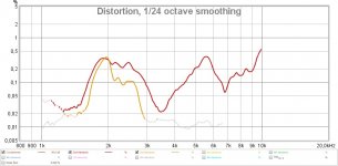
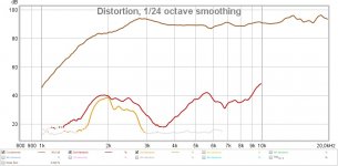
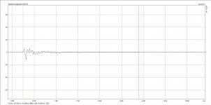
Today I put the HF108 in the Synergy-Horn and compared it against the HF10AK. The result is that the HF108 is clear the better one using in the synergy Horn with a crossover point between 1,5-1,8khz. Distortion below 2,5khz is a lot lower which results in extremely low distortion for the complete box (crossover 450hz/1,6khz). See measurement at about 95db/1m. The important area 1-4khz K3 is below 0,1%. Now also the Distortion peak at 2khz has gone away. The speaker now sounds more relaxed. So I will go with the HF108. I will do measurements under different angles next days.
Today I put the HF108 in the Synergy-Horn and compared it against the HF10AK. The result is that the HF108 is clear the better one using in the synergy Horn with a crossover point between 1,5-1,8khz. Distortion below 2,5khz is a lot lower which results in extremely low distortion for the complete box (crossover 450hz/1,6khz). See measurement at about 95db/1m. The important area 1-4khz K3 is below 0,1%. Now also the Distortion peak at 2khz has gone away. The speaker now sounds more relaxed. So I will go with the HF108. I will do measurements under different angles next days.
Attachments
-
 Distortion_HF108_with_Filters_and_Highpass.jpg407.6 KB · Views: 165
 -
 Distortion_HF10AK_with_Filters_and_Highpass.jpg410 KB · Views: 179
 -
 Frequency_Response_HF108_with_and_without_Filters_and_Highpass.jpg229.9 KB · Views: 192
 -
 Frequency_Response_HF10AK_with_and_without_Filters_and_Highpass.jpg232.1 KB · Views: 199
 -
 Distortion_Speaker_with_HF108_95db-1m.jpg446.5 KB · Views: 151
Last edited:
So I will go with the HF108. I will do measurements under different angles next days.
Please do. Very interest in variance.
My experience with straight sided synergies is that response variations across the mouth, at any distance from at the mouth out to 3m, is great enough that there seems little point in analyzing little response peaks and such....
Most of my tuning work goes into finding what particular measurement location, or locations' average, to use for corrections.
That said, all my builds have been on the larger side...maybe it's different if not so large..
By using the dual channel measurement feature of ARTA you can can see in the impulse response which driver is arriving first and by how much if you measure both drivers separately without moving the mic position. The propagation delay will be the same and you will be able to see the relative difference between the drivers.OK now the difficult question. How to time align them and match phase to each other? We have two different filters (LR4 on midrange and LR8 on tweeter) at two different electrical crossover frequencies (2000Hz and 1570Hz).
The first question for me. Do I have to delay the tweeter or the midrange? normally midrange is physically nearer to the listening position (delay midrange?) but I have heard the distance is longer because the sound is first going to the horn throat, getting reflected here and then runs through the horn to the listening position. If going this way I normally should delay the tweeter.
But is this correct? How to do this correctly step by step?
In general. I have heard the LR8 will not sound as good as LR4 because of the multiple phase changes. Is this correct?
Problem is that the midrange is falling already very step by it´s own so I need to use those step filters.
ARTA is a good measuring program but not so capable when it comes to crossover and EQ manipulation. If you do take polar measurements then Vituix is a very good program to learn to use as you will be able to see the changes across all angles when you adjust parameters.
REW has an alignment tool which works really well at aligning the phase between two measurements at a point. You can vary the crossover point and see which point gives the best phase match. REW can adjust the delay for you automatically or you can adjust yourself to see the effect. For this to work properly any fixed propagation delay should be removed from the measurements. REW can import the Impulse responses measured in ARTA but I don't know if the timing between drivers will be preserved doing it that way as I have never tried.
I posted some information here which shows some screenshots of it to give you an idea
Active LR4 crossover phase matching using a DSP
What really matters is the measured acoustic slope whether that is by using an electrical filter, acoustic roll off or combination it doesn't matter.
An option that you could try is to use parametric EQ on the mid response. You might be able to introduce a more gentle slope at the start of the crossover and then have it steepen as it goes up in frequency.
Another useful strategy can be to create synthetic target curves in rephase of the different crossover slopes to see how close your measured acoustic response is to the target. Using PEQ to match the curves more closely will get closer to the simulated target.
If you wanted to test the audibility of the phase wrap from the 48dB crossover you can generate a rephase filter to undo it. If you have a computer that can run a convolution filter you can test it with and without to hear if there is a difference.

I am currently looking around for matching twelve inch woofers for D'Appo-arrangement around the Synergy-Horn.
They should run in ClosedBox (about 50-60 litres for both) and will be crossed at about 70-80Hz to a DBA-Subwoofer system.
By further distortion measurements of the synergy horn I came across to cross a bit higher to the 12 inch woofers at about 500-600Hz to keep distortion of 4NDF34 in the Synergy Horn low.
Currently I am considering:
Faital 12FH520
Faital 12PR320
PHL 4531
PHL 4511
Beyma 12lx60v2
LaVoce WAF123.01
Eighteensound 12LW1400
Eighteensound 12W700
B&C 12PLB100
Any suggestions for best 12 inch woofer?
They should be in the 200€ range.
No one any recommondations?
Does anybody know if Ciare Woofers will be still availble in future (now as they belong to B&C)?
They have a few woofers with great data for my needs (low le, high qms, low mms, low rms, qts not to low to run in closed box) like NDC 12-3, NDK-12-3
Does anybody know if Ciare Woofers will be still availble in future (now as they belong to B&C)?
They have a few woofers with great data for my needs (low le, high qms, low mms, low rms, qts not to low to run in closed box) like NDC 12-3, NDK-12-3
Last edited:
Currently I am very happy with my prototyp, but still looking for improvments I can make on the next prototyp print to compare to current build.
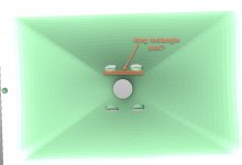
Is there maybe an improvement I can make with the form of the input slots?
Currently I am using round input slots (two on each side). Did anybody compare diffent input slot forms? maybe using rectangle long input slot helps me to put it nearer to compression drivers or maybe use oval input slots?
Is there maybe an improvement I can make with the form of the input slots?
Currently I am using round input slots (two on each side). Did anybody compare diffent input slot forms? maybe using rectangle long input slot helps me to put it nearer to compression drivers or maybe use oval input slots?
Attachments
What's the diameter of the round slot? Are they same size for the 4 inches and a larger size like a 6 ins or 8 ins midwoofer?
diameter of the round slots are 1,74cm each. They are all the same size.
Two of them for each 4NDF34.
Which means 4,75cm² (2*0,87*0,87*3,14) input port area for each 4NDF34 which means a compression ration of 1/12 (sd=57/4,75cm²).
Two of them for each 4NDF34.
Which means 4,75cm² (2*0,87*0,87*3,14) input port area for each 4NDF34 which means a compression ration of 1/12 (sd=57/4,75cm²).
Sorry I cannot follow. Can you explain more detailed what you mean?same size for the 4 inches and a larger size like a 6 ins or 8 ins midwoofer
Sorry what I meant, for a larger woofers like a 6 ins or 8 ins do I need to have a bigger slot (holes)? Thanks.
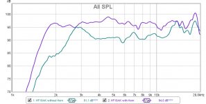
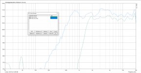
if you are using bigger drivers VTC,ATC and SD will increase and to have the same frequency response you should also increase the overall input area to have the same relation to sd/vtc. You can simulate this with hornresp. See my first post. There I have put screenshots which field in hornresp will contain which data. That was another reason why I changed from 5 inch to 4 inch to use smaller ports which will be better for the tweeter, because less holes in the horn will let the tweeter see more horn surface which should be better. Just for my interessting I have made a measurement of the tweeter in my synergy horn. Then I put tape over the input slots and measured again to see which effect the input slots will have to the tweeter (see attached measurments). For me it seems that the small input slots (because I am using 4 inch drivers now) have really less influence to the tweeter.
Back to topic: Anyone did some comparison between the different input slot forms? Any idea what I can improve here?
Back to topic: Anyone did some comparison between the different input slot forms? Any idea what I can improve here?
Attachments
- Home
- Loudspeakers
- Multi-Way
- Two way synergy Horn