Measurments - Angles
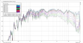
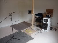
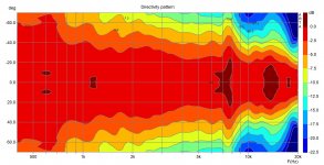
Today I have done measurements under different angles of Midrange-Tweeter-Section in the Synergy-Horn with all filters applied and with highpass at 550hz. Measurment was done with a rotatable plate in room gated to first room reflection which should result in measurements 400hz and above. One problem seems to be that the dispersion verticaly below 800Hz seems to widen up extremly. My plan was to use two 12 inch drivers in D'Appo around the horn crossed at about 550Hz which should then result in a "Peak" vertically between 550 - 800hz or?
Today I have done measurements under different angles of Midrange-Tweeter-Section in the Synergy-Horn with all filters applied and with highpass at 550hz. Measurment was done with a rotatable plate in room gated to first room reflection which should result in measurements 400hz and above. One problem seems to be that the dispersion verticaly below 800Hz seems to widen up extremly. My plan was to use two 12 inch drivers in D'Appo around the horn crossed at about 550Hz which should then result in a "Peak" vertically between 550 - 800hz or?
Attachments
Last edited:

Polars look great!My plan was to use two 12 inch drivers in D'Appo around the horn crossed at about 550Hz which should then result in a "Peak" vertically between 550 - 800hz or?
Not quite sure what your question is. The horn's smaller vertical dimension results in a loss of pattern control at a higher frequency than the horizontal. A 12" may be slightly less "omni" at 550 Hz.
Around the crossover frequency the combined on axis output (lobe) of the horn and woofers, if time aligned, should be at maximum, and cover a fairly wide vertical "window".
Last edited:
Missmatch vertikally
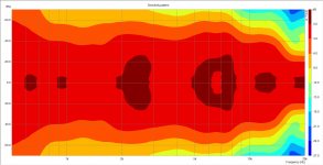
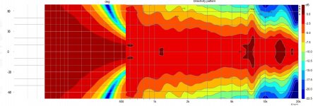
What I mean is that vertically the horn is widening up the dispersion below 700hz. When using two woofers in D'Appolito configuration around the horn the vertical dispersion of woofers is a lot lower (more beaming) which is the benefit of the D'appo-configuration to reduce reflexions (especially in the bass-region) of bottom and ceiling.
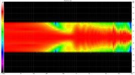
Attached is the polar map vertically of the synergy horn again but now from 400hz and above.
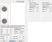
Also I have used boxsim and placed two 12 inch woofers (Visaton W300 because they are measured and included in Boxsim) in D'Appolito configuration to simulate the vertical polar response in Boxsim. Then i scaled both to the same size and dragged and dropped them over at the crossover region (550hz).
If simulated correctly this will result in "peaks" in the polar map between 400-800hz which maybe can be a problem.
I am wrong or did I an mistake in the simulation?
I am currently considering one 15 inch woofer instead one 12 inch woofer to avoid this problem.
What I mean is that vertically the horn is widening up the dispersion below 700hz. When using two woofers in D'Appolito configuration around the horn the vertical dispersion of woofers is a lot lower (more beaming) which is the benefit of the D'appo-configuration to reduce reflexions (especially in the bass-region) of bottom and ceiling.
Attached is the polar map vertically of the synergy horn again but now from 400hz and above.
Also I have used boxsim and placed two 12 inch woofers (Visaton W300 because they are measured and included in Boxsim) in D'Appolito configuration to simulate the vertical polar response in Boxsim. Then i scaled both to the same size and dragged and dropped them over at the crossover region (550hz).
If simulated correctly this will result in "peaks" in the polar map between 400-800hz which maybe can be a problem.
I am wrong or did I an mistake in the simulation?
I am currently considering one 15 inch woofer instead one 12 inch woofer to avoid this problem.
Attachments
Last edited:
You did not make a mistake, the further apart you space the drivers vertically the narrower their combined directivity vertically. This is always a trade off in MTM designs either the CTC needs to be smaller, the crossover point lower or the lobes can make it into the response. When the two are crossed over together it will not look as bad as it does when spliced in an image though.
Last edited:
ok, what is your opinion, would it be good idea using 2x 12 inch in dappo crossed at 550hz? I don´t really know how "bad" it is to have a "small" peak there in dispersion or better to say, is the benefit of low dispersion in bass (which reduces room reflections which especially in bass region are hard to handle) higher than the disadvantage of non constant coverage in the 400-800hz range?
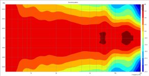
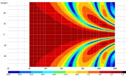
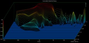
Attached is also the Cumulative Spectral delay which I have also measured gated in room of the synergy horn. I am not really a specialist in reading this diagram. It seems that there is a small problem between 1-2khz?
Attached is also the Cumulative Spectral delay which I have also measured gated in room of the synergy horn. I am not really a specialist in reading this diagram. It seems that there is a small problem between 1-2khz?
Attachments
Last edited:
Hi, this is the point of multiple entry horn, to get drivers close enough. There really is no other way if you use a waveguide than make them all inside the horn.
It does not match the synergy principal very well but that is not to say it can't be made to work or sound good. There are things that can be done to smooth the transition, some information here VituixCAD and examples on the next page. I would simulate the effect of the MTM with your measured horn data in Vituix to see what the overall result would be. There is a directivity mismatch there but all vertically separated drivers will suffer from lobing or nulls to some extent. The match in the horizontal directivity is more important so I would choose the crossover frequency based on that.ok, what is your opinion, would it be good idea using 2x 12 inch in dappo crossed at 550hz? I don´t really know how "bad" it is to have a "small" peak there in dispersion or better to say, is the benefit of low dispersion in bass (which reduces room reflections which especially in bass region are hard to handle) higher than the disadvantage of non constant coverage in the 400-800hz range?
There is a resonance there in the 1 to 2K range but it doesn't look too bad and it is best to look at it with crossover and EQ in place.Attached is also the Cumulative Spectral delay which I have also measured gated in room of the synergy horn. I am not really a specialist in reading this diagram. It seems that there is a small problem between 1-2khz?
Simulation VirtuixCAD
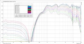
great hint with VirtuixCAD! I now managed to import my responses measured with Arta (SynergyHorn) as well as the BoxsimSimulation (12 inch in dappo) into VirtuixCAD and set the crossoverpoint to 550hz (4th order) in VirtuxCAD.
This results in the following combined polar pattern vertically which as espected has the peak.
Attachments
Maybe look at how Follgott managed to control the dispersion in this thread Pseudo-coaxial with narrow directivity (and Horbach-Keele filters)
Currently I am considering:
Faital 12FH520
Faital 12PR320
PHL 4531
PHL 4511
Beyma 12lx60v2
LaVoce WAF123.01
Eighteensound 12LW1400
Eighteensound 12W700
B&C 12PLB100
Any suggestions for best 12 inch woofer?
They should be in the 200€ range.
2cents:
I`m using a pair of 12FH520`s in my MEH/Synergy. Really loving the low mass (less enclosure movement) and clean sound, but didn`t compare to anything else. I do work in the industry though.

Any suggestions for best 12 inch woofer?
They should be in the 200€ range.
Eminence Deltalite-II-2512 | HiFiCompass
- Home
- Loudspeakers
- Multi-Way
- Two way synergy Horn