An opinions about 4x3 inch vs 2x5 inch?
Which 3 inch woofer you would recommend?
For the build you've been describing, I would use four 3" for all the reasons you spoke of.
May I call them midrange drivers, rather than woofers?
I think you will be able to get to 1.5kHz ok, especially when you get the their ports closer to the center of their cones. I found this really helped raise response higher...surprisingly more so than reducing volume under the cone.
Imho, putting ports under the surround is a compromise, albeit one often necessary for 1/4WL spacing.
Earlier, in post #5, you asked if 1/4WL between mids to CD, the distance to the throat or to the diaphragm. Great question, often discussed.
Dang if i know, and this is even after the chance to ask TomD this exact question in person. Loosely quoting, he said 'to the throat, and to think about it, all the sound is going out'.
I said ok, thinking it would get clear after mulling it, but it hasn't become clear at all for this old dummy 😕😛
If fact, I'm more confused than ever, because careful measurements always place the apparent acoustic center of the CD in front of the mid low drivers apparent acoustic center. Go figure....
This timing phenomenon has been on 6 different horn patterns and port placement schemes, corners vs centers. With No filters in place for timings.
All used a coax CD crossing at 500-650Hz, straight to mids designed to reach down to 100Hz. Pairs of mids varied from 12" to 8".
I continue to get near perfect, flat mag and flat zero phase response, using pure time delays applied to the CD as per the above timing measurements.....
(FIR tuning with linear phase xovers that don't introduce any relative delay between driver sections.)
As far as the frequency of the notch being the best way to determine, I guess that's it. Because timing's sure don't seem to match up with either distance.
Anyway,.... to the throat?, or to diaphragm?..... i plain dunno !!!!
You can record the time of flight of a CD to work out how long it appears to be. Some drivers like the BMS ring radiators have a really long time of flight and add quite a lot of apparent length to the simulation which if not accounted for at S1 will give an inaccurate prediction. BMS actually told me this information for a few of their drivers when I emailed them.
This affects the reflection notch from the CD which can be more of a problem than the rolloff of the bandpass ports. If you look at the ports Tom uses the frustrumizing makes the length of the port quite short and adds a little bit of throat chamber volume back. Try a 5 to 6mm port length and see what Vtc is needed.
It is hard to get the mids to play high enough if the CD can not go low enough and this is the struggle that everyone goes through when trying to use small midranges close in.
I bought and still have somewhere 2" Aurasound NSW drivers to use for this as they have a lot of xmax and thermal capability for their size and if 4 are used on a horn that is not too wide then they can get to 300Hz at a very high SPL.
The sensible option is to use a big CD that can play low and put the ports further out. Otherwise a CD like the BMS4550 that Tom used, makes sense as it has good output down to 800Hz.
Other options can work but success is certainly not guaranteed.
Simulating with ABEC/Akabak taps in an Ath horn in the resolution and mesh continuity needed to draw any reliable conclusion is quite a bit of effort 😉

FWIW, Altec told me in '68 that the acoustic center sets on the face of the phase plug [narrow gap between it and the diaphragm], but published it as the center of the VC like a point source driver at rest since it was well within the 1/4 WL rule.
Fast forward to the late '90s? and Tom Danley said he'd measured the same when somebody told me I was clueless, so not sure if he was phrasing it a bit different or if some newer CD designs are different than the typical 'classic': http://www.lansingheritage.org/images/altec/specs/components/802d-804a/page1.jpg
Fast forward to the late '90s? and Tom Danley said he'd measured the same when somebody told me I was clueless, so not sure if he was phrasing it a bit different or if some newer CD designs are different than the typical 'classic': http://www.lansingheritage.org/images/altec/specs/components/802d-804a/page1.jpg
I used Faital pro 3FE25 (Ferite version) in my build and only got a crossover point of 1.27kHz. Seemed like the HF was limited by the mass corner frequency so perhaps a driver with more motor force would go higher.
A good ROT for driver selection is Fh = 4*pi*Fs tuned to Fc = [Fl*Fh]^0.5, so is Fs a bit lower than published?
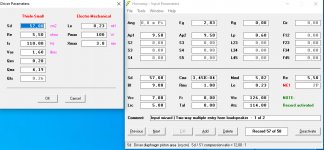
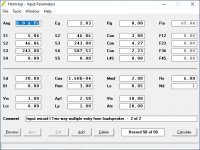
I modelled a bit more and it turned out that the B&C 4NDF34 seems to be a very good idea. I modelled my horn with two of them (2x 8 Ohm parallel = 4Ohm) and they are louder than four of the 3fe22 (4x 4Ohm; 2P2S = 4 Ohm) (104db instead of 99db) and the maximum spl of them is also louder than four of the 3fe22 (124db vs. 117db). Also they are just big enough to put them on my up- and downside. I tried to manage to put them as near as possible to the throat which results in that the distances of the input slots (middle to middle) are very good and should work for 1,5khz crossover. Also using the 4NDF34 allows me to put the input slots not over the surround. Looks promising so far. Maybe I will make an test-print. Volume-Fillers in Chamber are currently missing because I do not have the driver to measrue exactly the cone. Any recommondations?
Attachments

Last edited:
A good ROT for driver selection is Fh = 4*pi*Fs tuned to Fc = [Fl*Fh]^0.5, so is Fs a bit lower than published?
Good question I will have a look at the impedance data I measured for my drivers tonight. I do think its something to do with the driver though as 1.27kHz is well below the cancellation notch and filling the chamber volume had only a small change in response.
Another question. When building the version I just posted with two 4NDF34 I would pick a wooden case completely around the horn for the two 4NDF34 which means that the two 4NDF34 will play in around 7 litres closed box. This will result in a realtive high Q about 0,317. I don´t want to build custom "coffee mugs" for the drivers because it´s lot of effort doing this. Is there a disadvantage in midrange quality when runing them in "too much" litres?
I'm not the best to ask about modeling or how T/S parameters work.
But i just add foamboard blocks cut to fit to take up excess volume, when model says to, and then compare before and after measurements for overall shape of response.
No clue if it really effects quality that much, other than shape of response curve.
But i just add foamboard blocks cut to fit to take up excess volume, when model says to, and then compare before and after measurements for overall shape of response.
No clue if it really effects quality that much, other than shape of response curve.
You can record the time of flight of a CD to work out how long it appears to be. Some drivers like the BMS ring radiators have a really long time of flight and add quite a lot of apparent length to the simulation which if not accounted for at S1 will give an inaccurate prediction. BMS actually told me this information for a few of their drivers when I emailed them.
This affects the reflection notch from the CD which can be more of a problem than the rolloff of the bandpass ports.
Yes, the BMS ring radiators have a longer physical path length than dome diaphragms.
It was one of my concerns when studying synergies before beginning any builds. And why i asked TomD at a trade show what distance to use in figuring the reflection notch. He was adamant it is the distance to throat throat.
Another thing, and an even bigger puzzler to me are measured flight times to the CD compared to the mids.
Sorry i didn't express this well in previous post, but when i measure the raw flight times of the CD and the mid drivers from the same mic position outside the horn mouth, the CD has always measured less flight time, closer to the mic than the mid drivers
Generally the CD measures around 0.5ms closer to mic.
It varies a little between H to V patterns, and port placements, but not very much. Port centers have been between 5-7" from CD mounting flange (throat)
That's why i said "go figure"
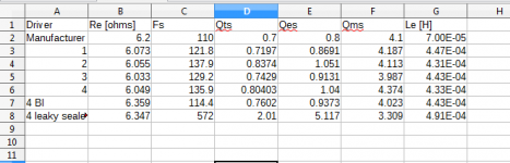
Ok so I had a look in my data for the 3FE25 and I don't have the original impedance sweeps just a table of some results. It looks like the big difference between the manufacturers specs is the inductance?
*not sure what 4Bl is
**leaky sealed is when I taped over the back of the basket
*not sure what 4Bl is
**leaky sealed is when I taped over the back of the basket
Attachments
I used four of the 4NDF34 in a one cubic foot gross volume MEH, they have around 3.5 liters apiece. Also tested them in a "coffee mug" box about 4" x 4" x 4" interior, about 1.3 liter. I'm using one 4NDF34 in a 4.5 liter box for my home theater center speaker run full range, no HP filter.I would pick a wooden case completely around the horn for the two 4NDF34 which means that the two 4NDF34 will play in around 7 litres closed box. This will result in a realtive high Q about 0,317. I don´t want to build custom "coffee mugs" for the drivers because it´s lot of effort doing this. Is there a disadvantage in midrange quality when runing them in "too much" litres?
The smaller box rolls off at a higher frequency, and limits excursion, but even in the larger cabinet volume, the 4NDF34 does not sound distressed when pushed beyond Xvar (5.7mm).
On the MEH, used a 1/4" standoff (about 5mm) which seems to be enough to keep the surround from hitting no matter how much voltage the driver sees.
With no cone filler, probably could cross as high as 1600Hz, 1500Hz should be good with the cone contour filled to within 5mm.
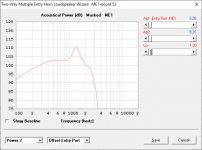
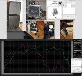
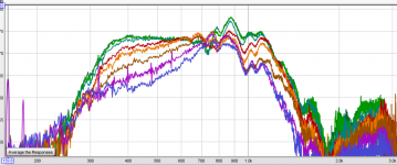
The green trace below is the 4" cube box, the purple is the four drivers on the dual PA60 "Boat Horn", raw response. The 4NDF34 ports enter about 2/3 the distance from the folded horn throat to the mouth, resulting in little horn gain and response dips. I had originally planned to cross around 450 Hz to the PA60, but the 4NDF34 sounded so much cleaner at high volume I raised the passive crossover to 900 Hz.
Covering 300Hz-1500 on a MEH, two 4NDF34 will probably outrun any 1" exit HF driver.
Art
Attachments
Last edited:
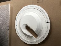
I now have the contour of the cone and surround for the 4NDF34 and now could model with correct VTC values in hornresp. And now simulation does not look so good anymore because VTC is more then expected and also need to offset the driver a bit for excursion. It´s really a mess. If I move the driver nearer to the horn to get shorter Ap1 the horn walls gets to thin for 3d printing. If moving back and horn walls are ok, Ap1 gets to long and frequency response is falling down rapidly at 1khz (regarding hornresp). Sure I can imporve with space fillser in chamber to reduce VTC but really difficult to get all these values together to get a nice simulation and also a solid horn surface for 3d printing.
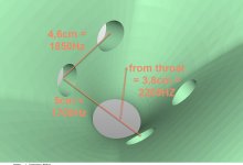
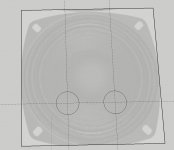
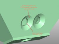
To minimise this issue is it maybe an solution to flatly reduce the input slots with a second ring around them like in the picture attached?
Hoping that the reduced ring around the offset "is seen" by the driver just as space belonging to VTC volume and just the small inner ring "is seen" by the driver as Ap1. That would make it possible to make thick horn walls but shorter ap1 Offset ports. Does this work as I expect?
Attachments
I used four of the 4NDF34 in a one cubic foot gross volume MEH, they have around 3.5 liters apiece. Also tested them in a "coffee mug" box about 4" x 4" x 4" interior, about 1.3 liter. I'm using one 4NDF34 in a 4.5 liter box for my home theater center speaker run full range, no HP filter.
The smaller box rolls off at a higher frequency, and limits excursion, but even in the larger cabinet volume, the 4NDF34 does not sound distressed when pushed beyond Xvar (5.7mm).
On the MEH, used a 1/4" standoff (about 5mm) which seems to be enough to keep the surround from hitting no matter how much voltage the driver sees.
With no cone filler, probably could cross as high as 1600Hz, 1500Hz should be good with the cone contour filled to within 5mm.
The green trace below is the 4" cube box, the purple is the four drivers on the dual PA60 "Boat Horn", raw response. The 4NDF34 ports enter about 2/3 the distance from the folded horn throat to the mouth, resulting in little horn gain and response dips. I had originally planned to cross around 450 Hz to the PA60, but the 4NDF34 sounded so much cleaner at high volume I raised the passive crossover to 900 Hz.
Covering 300Hz-1500 on a MEH, two 4NDF34 will probably outrun any 1" exit HF driver.
Art
Wow that looks like an massive system. When looking at your measurements it seems to be ok to run two of them in 7 litres.
Are you happy with the 4NDF34? Sure they can be very loud but how do they sound in your opinion? I will use them in my home cinema and not for PA-usage, so running them to absolute SPL and xmax is not necessary for me.
Anyone has made distortion measurments of the 4NDF34? Does anybody know if they are using demodulatoin rings?
Just about every thread I’ve come across related to building a synergy horn has recommended frustrums (beveled edges) around ports for mids and woofers.
Bill Waslo discussed it a little in the pdf relating to his spreadsheet/Cosyne article.
I believe he also assumed this added volume to vtc...can’t remember if he said anything about it reducing port length or not.
Regardless, I always assumed this was also to aid in preventing “huffing” as one rounds over ports in a bass reflex design for the same reason.
In my experiment, it was difficult to do while trying to build volume fillers into the driver mounts. I did the best I could.
Attachments
Last edited:
I'm very happy with the performance of the 4NDF34. As well as being capable of producing an amazing amount of SPL (for a 4") and handling loads of power without sounding distorted, the 4NDF34 also sounds really good at conversational levels.Are you happy with the 4NDF34? Sure they can be very loud but how do they sound in your opinion? I will use them in my home cinema and not for PA-usage, so running them to absolute SPL and xmax is not necessary for me.
Anyone has made distortion measurments of the 4NDF34? Does anybody know if they are using demodulatoin rings?
At the two meter distance from my center home cinema speaker, my hearing will distort before the single 4NDF34 will ;^).
No mention of demodulation rings in the spec sheets, probably not needed with the neodymium magnet structure.
Art
Last edited:
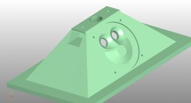
ok next try. Simulates very well in hornresp, if assumtion, two posts ago, that first circle belongs to VTC volume and only second ring assumed as ap1 length is true. Solit horn walls with at least 5mm (on weakest point). Maybe this will be my first prototype print.
Attachments

I have simulated the excursion in hornresp. When crossing at 250Hz/2nd Order at 200Watt (100 Watt each driver) the horn is already at 124db/1m. The excursion is then at 1,7mm each driver. I plan to cross a little higher (maybe 300-350Hz) and I do not know if I will ever put 200Watt into this horn because using this in home cinema environment and not PA. I have now build the VTC-fillers that everywhere is 3mm excursion capable before hitting the chamber. I think that should be enough for my needs, or does anybody see any issues there?On the MEH, used a 1/4" standoff (about 5mm) which seems to be enough to keep the surround from hitting no matter how much voltage the driver sees.
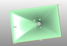
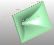
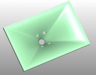
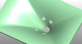
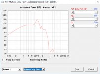
Regarding the xls-calculation-sheet for synergy-horn my 12 inch wide horn (11cm depth) will only hold directivity down to 800-900hz. But the midrange should at least run down to about 300hz where crossed to two 12 inch woofers (D'Appolito around horn). So does anybody knows what will happen to directivity between 300-800hz where midrange will run in horn, but horn is not able to control directivity anymore?
Below horn cutoff the baffle/enclosure takes over just like a normal speaker.
If your horn is flared such that as you get to larger angles you can't see the opposite side of taps in it any more you can get some directivity back at >1m, but it normally has gone omni before this point already, so it isn't that useful.
The image is this edge case.
The red line in 45deg.
If your horn is flared such that as you get to larger angles you can't see the opposite side of taps in it any more you can get some directivity back at >1m, but it normally has gone omni before this point already, so it isn't that useful.
The image is this edge case.
The red line in 45deg.
Attachments
Last edited:
3mm before contact should be plenty for your application, the compromise between HF extension and LF excursion fits your plan.I have simulated the excursion in hornresp. When crossing at 250Hz/2nd Order at 200Watt (100 Watt each driver) the horn is already at 124db/1m. The excursion is then at 1,7mm each driver. I plan to cross a little higher (maybe 300-350Hz) and I do not know if I will ever put 200Watt into this horn because using this in home cinema environment and not PA. I have now build the VTC-fillers that everywhere is 3mm excursion capable before hitting the chamber. I think that should be enough for my needs, or does anybody see any issues there?
That said, you could also use the same drivers for a "full range" center speaker (and surround speakers) which would not require using additional 12", so could fit below the cinema screen. In which case having the capability to hit Xlim without cone contact would be useful, as the excursion at 100 Hz would be much higher than the L/R speakers.
What does the simulation look like when the throat chamber distance is increased from 3 to 5mm?
Art
- Home
- Loudspeakers
- Multi-Way
- Two way synergy Horn