Just a small note - with a pair of 3FE22s in my Synergy AMT attachment I get the -3dB point a little below 1500 Hz. Which is good enough for the AMT.
Just a small note - with a pair of 3FE22s in my Synergy AMT attachment I get the -3dB point a little below 1500 Hz. Which is good enough for the AMT.
That sounds interessting. Are there measurments and/or pictures available of your build?
It is an eternal work in progress...on thid page there is the latest picture: ESS AMT-1 in my projects
Some more details on the previous pages. I will post my measurements later - as always, just quick and dirty. The frequency mentioned in the other thread is the knee beginning, -3 dB is a bit higher as mentioned above. There is no horn yet, so I expect some gain in the mids when it will be made.
Some more details on the previous pages. I will post my measurements later - as always, just quick and dirty. The frequency mentioned in the other thread is the knee beginning, -3 dB is a bit higher as mentioned above. There is no horn yet, so I expect some gain in the mids when it will be made.
I will place the speakers behind the cinema sreen. So placing 2x 12 inch woofers is not a problem.That said, you could also use the same drivers for a "full range" center speaker (and surround speakers) which would not require using additional 12", so could fit below the cinema screen. In which case having the capability to hit Xlim without cone contact would be useful, as the excursion at 100 Hz would be much higher than the L/R speakers.
I want to use exactly the same speakers (at least in the front) to make them sound coherent to each other.
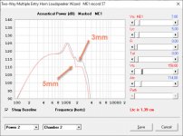
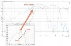
Increasing to 5mm will add 32,5cm³ to VTC (5,1cm * 5,1cm * 3,14 * 0,2 * 2). This let´s the frequency response fall more rapidly at about 1,8khz.What does the simulation look like when the throat chamber distance is increased from 3 to 5mm?
Attachments
Last edited:
De45dd,
Looking at your comparison between 3 & 5 mm, considering the small change in upper response, I'd still be inclined to use 5mm just to avoid any potential buzzing on peaks if you decide to lower the crossover point.
The speaker frame adds about 1mm clearance, using a 5mm spacer one way excursion available using the BC4NDF34 is about 6mm. The 4NDF34 Xvar is 5.7mm, but also seems very near the excursion limit, the surround rolls reach full extension without contact.
That said, using 3mm spacing, you could add gasket ring spacers after construction if you notice any buzzing on low frequency peaks.
Art
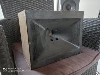
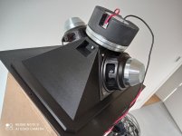
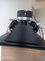
today my 3d printed prototype arrived. First lesson I have learned for the next time is to print the horn with the horn mouth to the upper side. Currently the Backside (which is in the box) is the "shiny" one and the horn side the "bad" one. For the prototype it´s not important. But for real speaker I would change it.
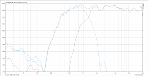
I have put the horn in a small box (about 6-7 liters) and did some quick and dirty measurements (20 cm in front of the horn in my room) without any filter applied to Midrange/Tweeter.
I am really surprised how good the frequency response looks like without any filter. And am also surprised how near the measured midrange response is on the simulated one. I think doing the effort modelling in honresp in detail (with a lot of mails to the hornresp developer) was worth it. What is also really good is that the downfall at 2khz which normally is always there with the HF10AK is not there in this horn. Maybe using the right exit angle in my with ath4 generated horn-contour has helped here eliminating this issue. I am currently using the 5mm offset version for excursion and crossing at 1,8khz looks really good. Maybe I do only a need a high-pass filter on the tweeter and that´s it.
Crossing at 350hz to 12 inch woofer should also not be a problem as well.
I will do some further measurements the next days with applied filters and under horizontal and vertical angles and will also have a look at distortion and waterfall but for first impression I am happy.
Attachments
Very nice ! Congrats !
i think what you're doing is the way of the future for DIY synergies.
The offset diff shows doesn't it. My guess is you might be fine with just a hpf to tweeter, although i'd probably add a paragraphic notch to the mids at 7.5kHz just cause the spike is there.
I'll be interested in how the 3d material ends up sounding to you....whether different from wood etc.
I would put a filter on the mid to get rid of the 7.5kHz peak. 1.8kHz is a nice high crossover frequency, these mids seem very special. To time align the drivers you will need to know the relative delay at your intended crossover frequency and (if using a passive crossover) use an asymmetric crossover slope to align them. In my case this resulted in the tweeter needing a higher order electrical filter than the woofers.
Where did you get the printing done, there is a no noticeable warping, its very good.
Where did you get the printing done, there is a no noticeable warping, its very good.
Over an octave of overlap in the crossover region using the 5mm standoff, excellent outcome!I am really surprised how good the frequency response looks like without any filter. And am also surprised how near the measured midrange response is on the simulated one... I am currently using the 5mm offset version for excursion and crossing at 1,8khz looks really good. Crossing at 350hz to 12 inch woofer should also not be a problem as well.
Congrats to you, ath4 and the printing.
Looking forward to the horizontal vertical & distortion measurements.
Art
compare VTC / offset
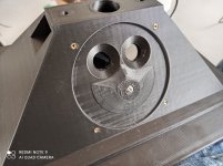
I have made the offset and the VTC-reduction adjustable to compare the different versions. Normally the offset is 3mm. To extend to 5mm I just use a small ring under the driver mounting place. The VTC-reduction is screw-able.
So I have now compared three different versions:
- 5mm offset without VTC reduction (highest VTC volume)
- 5mm offset with VTC reduction (middle VTC volume)
- 3mm offset with VTC reduction (lowest VTC volume)
What is not an surprise is that lowering the VTC volume will change the upper frequency response a bit. But is not that much that I thought.
What is more interesting to me is that, reducing the VTC volume seems to reduce distortion. The 3mm offset with VTC reduction has lowest distortion by a quick & dirty measurement (10cm in front of the horn at low listening level). I always thought it would be the other way around that reducing VTC (same as compression chamber at compression drivers) will improve SPL but result in higher distortion, that what I have heard from different people. But in my case it seems to be the other way around. Anyone has a idea what´s happening here?
Attachments
-
 Distortion_3mm offset + VTC reduction.jpg289.2 KB · Views: 248
 -
 Distortion_5mm offset + VTC reduction.jpg288 KB · Views: 239
 -
 Distortion_5mm offset without VTC reduction.jpg287.4 KB · Views: 274
 -
 Frequency_Response_Compare.jpg293.1 KB · Views: 326
 -
 VTC-Reduction_and_5mm_offset_extension.jpg353.2 KB · Views: 330

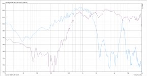
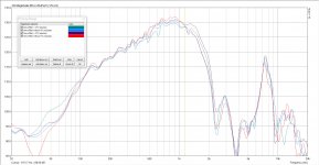
just to complete the range just measured the last possiblity (3mm version without VTC-reduction). To keep it simple to compare, here the complete line again.
From left to right (highest VTC to lowest VTC):
- 5mm without VTC-redcution
- 5mm with VTC-redcution
- 3mm without VTC-reduction
- 3mm with VTC-reduction
From distortion measurements perspective I am currently tending to 3mm offset with VTC reduction. When crossing at 350hz hoping nothing will happen with 3mm offset .
.
From left to right (highest VTC to lowest VTC):
- 5mm without VTC-redcution
- 5mm with VTC-redcution
- 3mm without VTC-reduction
- 3mm with VTC-reduction
From distortion measurements perspective I am currently tending to 3mm offset with VTC reduction. When crossing at 350hz hoping nothing will happen with 3mm offset
.Attachments
-
 Distortion_3mm offset + VTC reduction.jpg289.2 KB · Views: 374
 -
 Distortion_3mm offset without VTC reduction.jpg286.2 KB · Views: 339
 -
 Distortion_5mm offset + VTC reduction.jpg288 KB · Views: 351
 -
 Distortion_5mm offset without VTC reduction.jpg287.4 KB · Views: 378
 -
 Frequency_Response_Compare_new.jpg328.4 KB · Views: 367
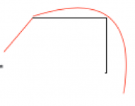
You mean maybe the 7,5khz dip comes from that?I wonder what it would look like with a smooth rollover instead of these sharp box edges...
//

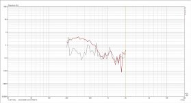
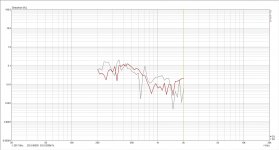
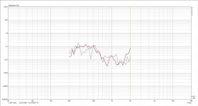
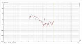
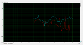
Distortion
Measured distortion at low listening volume with 1,4khz crossover.
Just hearing a bit with one speaker. Sound-wise midrange currently sounds a bit "hard" for first impression. Maybe I should give them a few days for softening the surround.
Measured distortion at low listening volume with 1,4khz crossover.
Just hearing a bit with one speaker. Sound-wise midrange currently sounds a bit "hard" for first impression. Maybe I should give them a few days for softening the surround.
Attachments
My understanding is reducing volume under the cone, while raising the lowpass freq, also makes for a more effective acoustic low pass filter.....which would of course reduce harmonics.

- Home
- Loudspeakers
- Multi-Way
- Two way synergy Horn