I am looking for test reviews of Linn LK1/LK2 like
Linn LK1 preamplifier & LK280 power amplifier | Stereophile.com
but together with Linn's outdoor power supplies for upgrade "SPARK" and "DIRAK".
Linn LK1 preamplifier & LK280 power amplifier | Stereophile.com
but together with Linn's outdoor power supplies for upgrade "SPARK" and "DIRAK".
Quick question: I would like to convert 2 LK280 to mono: one transformer per channel per box, increasing the capacitance to 20-30 mF per channel, eventually with external rectifier PCB to bypass the on-board diodes.
Would there be a problem with paralleling the transformer secondaries? I assume there shouldn‘t be any issues, impedance ratio and wattage is the same after all in both sets of secondaries.
How did the original Spark upgrade connect the secondaries of the LK280 transformer? I think they used the original transformer in the external case when upgrading, didn‘t they?
Thanks
Florian
For me new issue on a LK2-80 which I haven get today for repair.
Even second fuse in serial to the primär winding of toroidal transformer blown after few seconds.
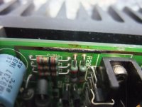
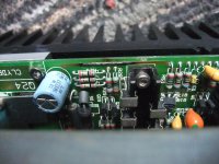
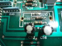
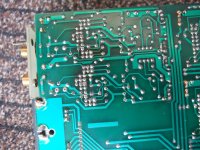
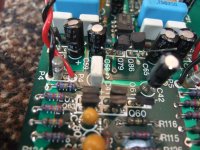
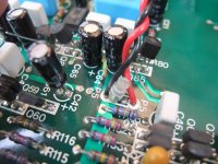
During a visual inspection of the left channel PCB I note a burned but not interrupt conductor track (go to the attached images).
This mentioned pad is connected to GND and on the PCB this pad interconnect pos. pole of C13 (100uF/63V) and R51.
R51 (not shown in the genuine schematic from Linn) belongs to the input low pass filter and attenuation combination R1, R2 and C1, go to page 6 and 7 on schematic of post #51, page 6 from this thread.
This is the first repair at this device, i. e. even the electrolytic caps are from the initial equipment.
Sanken's power devices 2SA1386/2SC2519, in use for power buffer and voltage regulator are not shorted.
Where should I start troubleshooting after performing the recapping procedure ?
Thanks for an advice.
Even second fuse in serial to the primär winding of toroidal transformer blown after few seconds.
During a visual inspection of the left channel PCB I note a burned but not interrupt conductor track (go to the attached images).
This mentioned pad is connected to GND and on the PCB this pad interconnect pos. pole of C13 (100uF/63V) and R51.
R51 (not shown in the genuine schematic from Linn) belongs to the input low pass filter and attenuation combination R1, R2 and C1, go to page 6 and 7 on schematic of post #51, page 6 from this thread.
This is the first repair at this device, i. e. even the electrolytic caps are from the initial equipment.
Sanken's power devices 2SA1386/2SC2519, in use for power buffer and voltage regulator are not shorted.
Where should I start troubleshooting after performing the recapping procedure ?
Thanks for an advice.
Attachments
Last edited:
Hi guys I have two faulty LK1 preamps,both have the infamous disco/Christmas tree problems on the control board
I was wondering if I could bin the control boards and put dom pots and switches in the main board to control volume, balance and inputs
I'm not a electronic genius like you guys on here so any advice would be very much appreciated
Thanks
I was wondering if I could bin the control boards and put dom pots and switches in the main board to control volume, balance and inputs
I'm not a electronic genius like you guys on here so any advice would be very much appreciated
Thanks
Through a leaked accu/battery such issues are occur.
Check solder joints and replace all electrolytic caps and remove the storage battery.
I am looking for a remote control as replacement - maybe one of the members have one in faulty condition.
If yes, mail me
kirschner-hifiatweb.de
check therefore also post #1 under
https://www.diyaudio.com/forums/ana...000-sl490-sl490b-linn-lk-1-a.html#post6589568
I explain an other possibility to find an appropriate RC transmitter.
Last edited:
Can anyone confirm Linn did a lot of mods to this design over the years but kept the same PCB? The amount of bodge wires and tacked-on parts is...rather disturbing. I've found pictures of another post-1990 LK1's that looked the same.
Even the PSU caps rather wildly, older ones have 2x4700uF and the later ones 2x10000uF.
Even the PSU caps rather wildly, older ones have 2x4700uF and the later ones 2x10000uF.
Last edited:
Yes - a lot of modifications was performed with same PCB.
This was in detail explain under
https://linfo.linn.co.uk
and here:
Oops! Page not found | Linn International
Unfortunately both URLs are dead - go to
Linn Forum is permanently closed - who have save all the Threads arround the LP12 ?
Maybe one of the members have save this details anywhere.
Check out also this:
LINN LK1 PREAMPLIFIER Service Manual download, schematics, eeprom, repair info for electronics experts
Linn LK 1 Vorstufe Reparatur - einige Fragen - Phono - Restaurierung und Selbstbau - Analogue Audio Association (post #6)
Last edited:
Burned PCB arround MC Pre-Pre in LK-1 - what can I do to remedy this deficiency ??
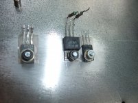
Important for this is to find out, which type of the same process are implement in a SOT32/TO126 outline (i. e. ZTX653/753 in TO126 outline) - go to
https://www.diyaudio.com/forums/par...-ztx753-ztx653-to126-outline.html#post6797005
Important for this is to find out, which type of the same process are implement in a SOT32/TO126 outline (i. e. ZTX653/753 in TO126 outline) - go to
https://www.diyaudio.com/forums/par...-ztx753-ztx653-to126-outline.html#post6797005
Supplement to post #71 of LK-1 Preamp Device, Ser.-No 109546
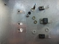
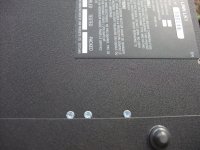
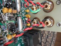
Various images concerning better cooling of the voltage regulator IC and associated transistors (images No 1-6), burning PCB of MC input area (despite only low operating hours, image No 7), disconnect voltage rails for MC input stage (images No 8+9, see my question in my previous post) MC input socket in parallel to MM input socket for the aim of use of cinch plugs with integrated resistor and capacitor to adjust the necessary cartridge load (last image).
Various images concerning better cooling of the voltage regulator IC and associated transistors (images No 1-6), burning PCB of MC input area (despite only low operating hours, image No 7), disconnect voltage rails for MC input stage (images No 8+9, see my question in my previous post) MC input socket in parallel to MM input socket for the aim of use of cinch plugs with integrated resistor and capacitor to adjust the necessary cartridge load (last image).
Attachments
-
 DSCF7704.jpg1 MB · Views: 267
 -
 DSCF7700.jpg1 MB · Views: 274
 -
 DSCF7709.jpg933.9 KB · Views: 407
 -
 DSCF7714.jpg1 MB · Views: 239
 -
 DSCF7719.jpg993.3 KB · Views: 246
 -
 DSCF7720.jpg1 MB · Views: 223
 -
 DSCF7722.jpg1,013.4 KB · Views: 240
 -
 DSCF7725.jpg998.5 KB · Views: 259
 -
 DSCF7727.jpg991.3 KB · Views: 268
 -
 DSCF7729.jpg946.7 KB · Views: 318
Last edited:
ON my LK280 i have both R4 and R51 burned... The amp caused a DC offset in the speakers so i replaced LM317 + LM337
OK R4 is 150 Ohm but what is the value of R51?
OK R4 is 150 Ohm but what is the value of R51?
- Home
- Amplifiers
- Solid State
- tweaking classic Linn LK1 & LK2 / LK280