ahh OK. Didn't gave much attention to wow and flutter getting in cassette tape while recording and off center of platter OD.
But shouldn't these be less compared to test records. I mean while cutting test on on master there must be some speed fluctuations.
Pardon for overthinking. How about measuring with both tape and test record and subtracting unnecessary data from both (for example offcenter of record and platter OD) to only get precise speed variation data ?
For total accuracy the platter circumference would need to be concentric with the bearing to quite a high tolerance.. if not we are back to our original issue i.e. off centre test records.
Certainly things like links and Kuzma are, anything with a machined outer edge or driven by platter edge.
How do you all feel about dropping the test record altogether and moving to an optical disk and reader? As rega have done for their current deck development.
How do you all feel about dropping the test record altogether and moving to an optical disk and reader? As rega have done for their current deck development.
Are any of the affordable CNC houses capable of making one, group buy?
I'm going to try and incorporate JP's excellent ideas with some minor changes into a new rev of the TT tool. I will be taking a week off to, among other things, listen to some live music with Jan and SY.
That's not necessary, magstrip taped around the edge of platter with Hall sensor will be more than accurate enough. Magstrip has position data also.Are any of the affordable CNC houses capable of making one, group buy?
Might be able to measure that from the field strength. If eccentric then the air gap will change. But I'm not sure how coupled record😛latter eccentricity is.
Scott, how many segments would you want?
Not sure, Others should comment too. 2wice, sorry I removed my comment to think about it more, the platter eccentricity from top vs side is a geometry thing.
Another option. To get rid of offcenter records etc.
All turntables would have a mat so we remove the mat replace it with larger (larger then 12") thin acrylic or metal plate with some kind of (Magnetic or optical markings* thing) on the edge, which can be measured by sensors. The acrylic or metal plate will have little large diameter center hole so it can be centered precisely adjusted with dial indicator. Place music record on it and if possible center weight and measure the data.
*A laser can cut precision holes. One side would have light source and the other side a sensor placed in a slit. which only reads single individual hole.
How do you join the ends exactly so that there isn't a discontinuity? Or is the discontinuity the reference?That's not necessary, magstrip taped around the edge of platter with Hall sensor will be more than accurate enough. Magstrip has position data also.
My SW doesn't use Hilbert transforms, and methodically is different. For whatever reasons, it doesn't suffer from strong out-of-band content issues, and LF noise rejection generally seem to significantly outperform the current version of the python sw.
So every encouragement to keep developing it and fix these issues: I think it's necessary and worthwhile.
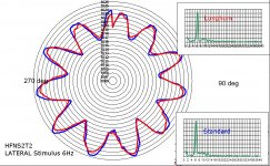
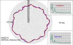
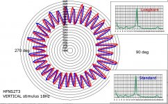
Here's a couple of polar plot reposts from earlier on the thread, showing the effect of playing a resonance test track near cart-arm resonant Fs. These were part of George's Longhorn mod tests, which seems to bury some demons.................
LD
So every encouragement to keep developing it and fix these issues: I think it's necessary and worthwhile.
Here's a couple of polar plot reposts from earlier on the thread, showing the effect of playing a resonance test track near cart-arm resonant Fs. These were part of George's Longhorn mod tests, which seems to bury some demons.................
LD
Attachments

The pole pieces are 2mm so max gap is tiny and can be fixed in software.How do you join the ends exactly so that there isn't a discontinuity? Or is the discontinuity the reference?
A turntable with the centre spindle stopping flush with the platter surface and a second spindle above it on a small actuator capable of +/- 1mm x and y shift. All controlled by wireless and using something like the test software to detect eccentricity from sustained notes on the record. It might work 😎Another option. To get rid of offcenter records etc...
Actually there is no need for centering by dial indicator if the acrylic/metal is precision cut.Another option. To get rid of offcenter records etc.
All turntables would have a mat so we remove the mat replace it with larger (larger then 12") thin acrylic or metal plate with some kind of (Magnetic or optical markings* thing) on the edge, which can be measured by sensors. The acrylic or metal plate will have little large diameter center hole so it can be centered precisely adjusted with dial indicator. Place music record on it and if possible center weight and measure the data.
*A laser can cut precision holes. One side would have light source and the other side a sensor placed in a slit. which only reads single individual hole.
I get plastic laser cut and engraved often enough. But I have no idea if it's precise enough to make a reference disc. Does anyone know how precise laser engravers tend to be?
Not sure, Others should comment too. 2wice, sorry I removed my comment to think about it more, the platter eccentricity from top vs side is a geometry thing.
First of all thank you (all) for a most interesting thread
Where does my thinking goes wrong?
At 33rpm a point at the rim of a 30cm outer diameter disc travels at a speed of approx. 0.52 m/s. ( (PI * 30cm/ (60s /33rpm) )
The SP10 Mk3 spec of 0,015% on each point that passes, so not on a full round, would lead to a spacing of 0.078 mm.
The test records used with a signal of 3150Hz give you one full sinus over 0,165 mm. Two peaks 0,082 mm apart. With 40kHz sampling somewhat over 10 samples 🙂
My thinking last week:
The route with a hall sensor will give you "global" information.
Visual systems will be very costly to make at this level of accuracy
Cost effective an Arduino gps accelerometer sensor based system with the right set of Kalman filters (etc) should be able to do the job at the outer end of the platter. That is not the place where you want to have it. At best would be on the outer rim of a puck/weight in the centre. Would the accuracy be at the required level?
The RPM type apps on our phone work on these principles question is how to get the continuous signal out.
Where does my thinking goes wrong?
Thanks
Michiel
PS I don't have the programming experience.
pardon I am little overthinking.
We can very well use cheap CD player. Put Tone Audio CD on platter. Somehow arrange CD reader (Upside down) so that it can read the test tone.
We can very well use cheap CD player. Put Tone Audio CD on platter. Somehow arrange CD reader (Upside down) so that it can read the test tone.
The route with a hall sensor will give you "global" information.
If the magstrip includes position data, won't you be able to calculate speed at any position?
- Home
- Source & Line
- Analogue Source
- Turntable speed stabilty