George: Thanks for the clarification, I couldn't see that on the shot. I too must do some dissection.
LD: If you look at other mass damper tech then you only need 1-2% of total mass in the damper. Think F1 Mass Damper or the Japanese building dampers. I am not sure most longhorn mods have either enough flex or damping to work properly, but the concept is sound.
LD: If you look at other mass damper tech then you only need 1-2% of total mass in the damper. Think F1 Mass Damper or the Japanese building dampers. I am not sure most longhorn mods have either enough flex or damping to work properly, but the concept is sound.
Longhorn or Stockbridge?
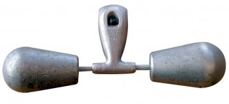
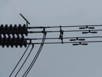
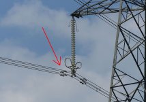
I am a retired electrical engineer and when I first saw the Longhorn cartridge modification it made me think of a device used by the electric utility industry, known as a “Stockbridge Damper”. A Stockbridge damper resembles a dumbbell and is commonly seen attached to the ends of high tension transmission line cables near the insulators on a tower.
Stockbridge dampers were patented in 1928 and are generically named after the inventor. Air blowing over high tension lines sets up a wake turbulence that causes the cable to vibrate in a range typically 5-17 HZ. The combination of the two masses with the stiffness and length of a multi-strand steel connecting cable tunes the damper assembly to the desired frequency. Energy is dissipated in the multi-strand steel cable via the friction effects of the individual strands rubbing against each other as the overall cable flexes. I was not able to find documentation on this, but recall hearing or reading that the lineman would tap the powerline with a hammer while moving the damper position back and forth to find the ‘sweet spot’ of maximum vibration attenuation before tightening the locking clamp.
For the curious, here’s a Wikipedia link:
https://en.wikipedia.org/wiki/Stockbridge_damper
Most Longhorn implementations appear to only add mass in the form of a solid bar, and none seem to have any damping element or means for dissipating energy. The concept has been around for a long time, and has been well refined for application in the electric utility industry. Phono cartridges and tonearms…?
Have I drifted off topic again?
Ray K
Attachments
I think that is totally on topic seen as everything comes back to resonance control. The original longhorn mod was posted here http://www.avahifi.com/images/avahifi/root/audio_basics/ab_pdf/ab1982.pdf starting page 9. But IMO the construction you have shown is the right way to go about it. Think tightrope walker.
(aside, the guys that work on live HT lines amaze me, I get enough heebies when I cycle under a supergrid line on a damp day and hear it humming and fizzing, but when you see people climb out a helicopter into a basket on the line!).
(aside, the guys that work on live HT lines amaze me, I get enough heebies when I cycle under a supergrid line on a damp day and hear it humming and fizzing, but when you see people climb out a helicopter into a basket on the line!).
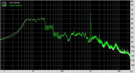
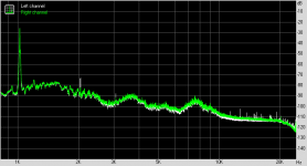
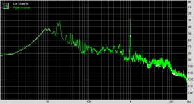
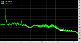
OK, I plotted them all. The difference between modified files is almost non existent, between stock and any mod there is a tiny difference way up high. But could you hear it?
Track 2 and track 3 shown below. Left channels is unmodified reference, right channel is the Longhorn with no extra weight. Also see a zoomed in view.
T2, T2 zoom, T3, T3 zoom
I'll upload the others tomorrow.
Track 2 and track 3 shown below. Left channels is unmodified reference, right channel is the Longhorn with no extra weight. Also see a zoomed in view.
T2, T2 zoom, T3, T3 zoom
I'll upload the others tomorrow.
Attachments
I don't understand what the longhorn mod is meant to achieve.... ie what exactly is meant to be twisting or flexing? As Bill says, nothing is dynamically rigid. However, I find it hard to understand the alleged dynamic motion with or without the stabiliser bar, unless there's some fault....?
LD
I don't get it either but I have wondered whether a unipivot arm, with its additional degree of freedom, might benefit.
Thanks very much LD.
Triangular tonearm
This is rudimentary design. how to make all three section tight fit should be possible.
Thanks and regards.
So if Headshell, cartridge and stylus body is tightly fit. Only horizontal movement bearing compliance would be important after suspension because it has lowest friction and only more moving part than other linkages of the tonearm ?in an otherwise healthy arm where nothing is loose or flexible, because there really shouldn't be anything near as compliant as the suspension elastomer.
An oval shape elastomer would probably be better ?Being an elastomer ring, it will be in compression due to VTF, and elastomers notorious non-linearity probably explains the rest. A factor of about x4 in vertical compliance verus lateral complaince is needed to explain the difference between 18Hz and 8Hz vectors, which just about seems plausible I suppose? Or maybe the tie wire is involved in this case?
For traansverse vibration one can use various damping material and for torsional vibration a triangular shape instead of tube would benefit. I had posted such design in another thread. your critique will be most welcome on all three thoughts.Tonearms, as cylindrical tubes, typically have a first resonant mode at which they become flexible around 200Hz for transverse vibrations, but far far higher than this for torsional vibration.
Triangular tonearm
This is rudimentary design. how to make all three section tight fit should be possible.
Thanks and regards.
and when I first saw the Longhorn cartridge modification it made me think of a device
Hi Ray
Thank you for bringing up the Stockbridge damper
Like you, I haven’t seen any intentional sympathetic resonance element in the original longhorn idea.
On the other hand, the modification necessarily adds some mass, something that will change some parameters in the whole mechanical system.
Which parameters are affected, I don’t know.
This is the reason that I have included options 3 and 5 in the test runs.
OK, I plotted them all. The difference between modified files is almost non existent, between stock and any mod there is a tiny difference way
Thanks Michael.
I’ve run 2M FFTs on the files and I can’t spot an indication of difference with this method.
My opinion is that whatever changes with this mod, it is to be found at the low or mid frequencies.
Listening tests is a key part in the investigation but it’s uncomfortably warm here and I don’t have the desire to do listening tests now. I have to postpone them.
George
http://avahifi.com/images/avahifi/root/audio_basics/ab_pdf/ab1982.pdf (pages 8-9) describes the original longhorn mod as published in 1982. The mod comprised a 1.5-inch length of brass U-channel. The ends were filled with solder to add mass, and the remainder of the channel was filled with damping material. Various audiophile goodnesses were listed as benefits, Probably the most reasonable was increased torsional inertia about the tonearm axis, which could help stabilize unipivot arms.
The longhorn mod seems popular with Grado cartridges, which have relatively low stylus suspension damping.
The longhorn mod seems popular with Grado cartridges, which have relatively low stylus suspension damping.
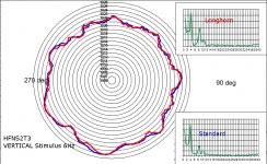
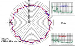
Longhorn versus standard pitch stability polar plots
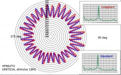
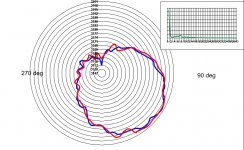
Attached are images that show, on the same chart, longhorn and standard polar plots for pitch stability. Red is Longhorn, Blue is standard. Inset are FM spectra for both traces. Carefully time aligned for same location on record - very nicely done George !
I just looked initially at 'standard' Shure, and Shure + longhorn files. For all combinations of lateral and vertical stimulus at 6Hz and 18Hz (which seem to be near to lateral and vertical cart-arm natural resonant frequencies ).
IMO there is no meaningful difference between standard and longhorn FM pitch stability in this test........I think if there were difference in unwanted headshell/cartridge motion it would likely show up here, but apparently doesn't.
I suspect we might well be looking carefully for something that doesn't exist - I can't see why it should........ but if any bright ideas as to what else to look for in those sweeps I'd be happy to have a look?
BTW, any small difference in resonant frequencies due to extra mass of the mod doesn't show up here, because the headshell motion adopts the stimulus frequencies since they are close to the natural ones.
Still very pretty and very interesting 😉
LD
Many thanks George for another set of excellent and careful recordings. I took a good look and ran some polar plots, to look at effects on FM modulation.Let’s put it to the test. What does it do in terms of modulation.
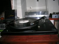
JVC QL- A2 with:
1 Shure
2 Shure+longhorn .......
Attached are images that show, on the same chart, longhorn and standard polar plots for pitch stability. Red is Longhorn, Blue is standard. Inset are FM spectra for both traces. Carefully time aligned for same location on record - very nicely done George !
I just looked initially at 'standard' Shure, and Shure + longhorn files. For all combinations of lateral and vertical stimulus at 6Hz and 18Hz (which seem to be near to lateral and vertical cart-arm natural resonant frequencies ).
IMO there is no meaningful difference between standard and longhorn FM pitch stability in this test........I think if there were difference in unwanted headshell/cartridge motion it would likely show up here, but apparently doesn't.
I suspect we might well be looking carefully for something that doesn't exist - I can't see why it should........ but if any bright ideas as to what else to look for in those sweeps I'd be happy to have a look?
BTW, any small difference in resonant frequencies due to extra mass of the mod doesn't show up here, because the headshell motion adopts the stimulus frequencies since they are close to the natural ones.
Still very pretty and very interesting 😉
LD
Attachments

Last edited:

You're welcome Pano. There seems no point in adding polar inertia in a plane that isn't free to rotate......🙄Well, that's all a bit underwhelming for the Longhorn, isn't it?
Thanks Lucky
Perhaps in some cartridges or arms, there might be meaningful torsional flexibility? But surely not generally, one would hope/think.........
LD
Gotta love science. This is possibly the first time this has been measured despite 30 years of people discussing it and trying it 🙂.
I was thinking the other day. A real time version of the polar analysis software (say LDtech PolarRT) would be the most amazing turntable tuning tool. Would blow Fieckert into a top hat.
I was thinking the other day. A real time version of the polar analysis software (say LDtech PolarRT) would be the most amazing turntable tuning tool. Would blow Fieckert into a top hat.
Attached are images that show,
Thank you Lucky. Much appreciated.
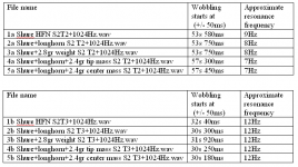
These tracks were meant to be tested through listening (the 1kHz tone starts to wobble when the arm/cart resonance is excited).
So I sat and listened to the recordings, trying to locate on each one the start of the 1kHz wobbling. It seems to me that for the S2 T2 files, the wobbling shifts a bit with the configuration.
I tried to locate the start of wobbling a bit more precisely by mixing one channel from each recording with a steady tone (1024Hz).
I upload the resulting mono files here
Dropbox - Mono files for dropbox
Here is my opinion (attachment).
Attachments
Can anyone answer my query ? When you people speak of headshell movement. Do you mean movements at headshell end or at bearing end. Looks like Tonearm with unibody like Rega would be good choice if movements is at headshell end.
Regards.
As promised
Rega 3 + Goldring Eroica through Musical Fidelity X-LP (MC) RIAA preamp
15/7/2017 13:00, 32.8d Celcius, 40.4% rel humidity.
Dropbox - Rega3 +Goldring Heroica L for dropbox
With a little help from Lucky 🙂 we’ll see what is going on.
George
Attachments
I had to download the Wiki link to find out the Stockbridge tweak was not invented in Edinburgh.
Some of our buses have a short history posted on the back giving the origins of "Stockbridge"
Some of our buses have a short history posted on the back giving the origins of "Stockbridge"
Thats wonderful gpapag. Cant thank enough for your efforts. Not only for this but your other measurements too. Eagerly waiting for LD's comments.
Thanks again and warm Regards.
Thanks again and warm Regards.
Hi George, thanks for this.As promised
Rega 3 + Goldring Eroica through Musical Fidelity X-LP (MC) RIAA preamp
15/7/2017 13:00, 32.8d Celcius, 40.4% rel humidity.
Dropbox - Rega3 +Goldring Heroica L for dropbox
With a little help from Lucky 🙂 we’ll see what is going on.
George
Here's the first of the analysis polar plots. It's the S1 T10 3150Hz tone.
The TT is running fast, and there's a strong 'once per revolution' variation that mimics eccentricity. Could be centering or vertical run-out, or bent spindle or something like that ? This effect is so bad that it's likely to mask anything else, and that shows up in the inset spectrum...
HTH !
LD
Attachments
Many designs were alleged to be intentionally fast for "a more exciting, dynamic sound"It's curious that all the files so far are fast. What's going on there?
- Home
- Source & Line
- Analogue Source
- Turntable speed stabilty