I tried your Audacity recipe @richgwilliams on the 17200 Hz recording that I made yesterday - it worked nicely! It may be that you are the first one to have used Audacity, and only linear analog circuitry besides that, as an offline SDR receiver.
My recording is here - the sound quality is more rough than yours. I guess it is a combination of laptop sound card noisiness and urban interference.
My recording is here - the sound quality is more rough than yours. I guess it is a combination of laptop sound card noisiness and urban interference.
@Aridace You have a lot of interesting experiences from the world of electronics, radio and communications.
I agree with you, the low impedance tap or winding is not so good. Back to an insulated gate FET or modern JFet OpAmp! But then the thermionic tube (or valve) has great application for a VLF front end and is again fashionable for audio preamps. Could be just one tube at the front end feeding into an Opamp, that would likely make a very low noise VLF receiver/amplifier indeed.
My way of designing and thinking can be very focused on solving the one problem rather than something more general. As can be seen from building a receiver/amplifier that is only designed, built and intended to pick up one VLF station.
Its very tempting to build an improved receiver amplifier in time for SAQ Grimeton's next transmission. My Morse code is improving, I know and recognize at least five letters and close to knowing another ten letters. With a Morse table I think I can decode about six words per minute.
NVIS sounds useful.
@richgwilliams Indeed, radios fitted with FET devices at the input have none of the problems of BJT. Generally the NF is better than of tubes but at VLF that's a nonissue especially when considering burnout probability of mos protection diodes in the presence of nearby lightning strikes (experienced that already). Interesting is that tubes can operate at lower supply voltage than indicated by the producer so for a VLF active antenna could be useful.
Because the power company in Panama regularly produces more RF energy (mostly at VLF) than all Panamanian MW stations combined, if I want to receive SAQ there's no alternative but to design an improved receiver. The horizontal lines on the pic (lowest spectrum waterfall), courtesy the power company. It suggest there's not only an AM but also an FM component. As the SDR has a set of tools available, the scope gives the (expected) display.

FM demodulator output, 50k BW:

At a different frequency:

Because the power company in Panama regularly produces more RF energy (mostly at VLF) than all Panamanian MW stations combined, if I want to receive SAQ there's no alternative but to design an improved receiver. The horizontal lines on the pic (lowest spectrum waterfall), courtesy the power company. It suggest there's not only an AM but also an FM component. As the SDR has a set of tools available, the scope gives the (expected) display.
FM demodulator output, 50k BW:
At a different frequency:
A JFET common-source stage with a diode in antiparallel with the gate-source junction should be reasonably well protected against peaks due to lightning.
oops, that is really impressive. In such environment I would add some series resistor 1~10k into the gate input. A THT-type not SMD. I would expect a ferrite antenna being less dangerous. You might consider gas surge arresters as well.
Last edited:
The experience was bad enough to redesign how the grid had to be treated at the entrance of the house. For VLF a series R up to 10k indeed works OK if physically large enough. I got a supply of gas surge arresters as well and burned through too many to consider continuation of the use. The solution to protect the house was to protect the MOVs with a thermal switch, and indicating the temporary disconnect with a LED. It works well, saw it various times in action (short interruption at a nearby strike while the LED lights up).
I tried your Audacity recipe @richgwilliams on the 17200 Hz recording that I made yesterday - it worked nicely! It may be that you are the first one to have used Audacity, and only linear analog circuitry besides that, as an offline SDR receiver.
That's great well done @fowlay !!
I downloaded your file telegram-17200.wav and had a look at the spectrum and yes there is more local noise. There is a lot of 50 Hz from the mains and a lot of power supply interference. The 50 Hz is probably an "audio earth loop" or a disconnected cable screen. The power supply noise is probably mostly from your Laptop or something else close nearby. I used a long audio cable between my Laptop and the receiver, also running all on battery.
Then I tried to process your file in Audacity - it took more notch filtering than my recording. I am attaching the audio file I made from your telegram-17200.wav recording.
Your recording is better because there is no "storm lightning" noise.
I also plotted the spectrum from your telegram-17200.wav file, the SAQ peak is about -60dB whereas I was getting -18dB, I think because I was using an outside antenna and a receiver resonant to 17.2 kHz.
Very interesting, the spectrum you have looks much more linear:-
Attachments

Thank you for saying that but its very hard to be the first at anything these days, there are many capable people around.It may be that you are the first one to have used Audacity, and only linear analog circuitry besides that, as an offline SDR receiver.
As I was saying to @Aridace "My way of designing and thinking can be very focused on solving the one problem rather than something more general. As can be seen from building a receiver/amplifier that is only designed, built and intended to pick up one VLF station"
As I said previously "For me it is all about respect for the Swedish Alexander Association"
FM demodulator output, 50k BW:
At a different frequency)
I have seen this kind of waveform here locally. Its not in the line voltage waveform, rather its in the line current waveform. I associate it with line current, with older type solar panel grid tied inverters (they feed current pulses into the grid) and with other things such as thyristor dimmers and motor speed controllers.
Are you certain that your antenna is actually receiving this noise by way of EM waves from a distance? Rather than something that's getting in with your equipment power supplies, earth loops, local magnetic fields from wiring/other nearby equipment.
Are you sure that equipment and antenna and earth are all well away from mains wiring, solar panel inverters etc. Are you sharing an earth connection or have you got a completely separate earth for your receiver. Lighting especially fluorescent tubes can radiate a lot of interference also.
If not already done, I would be thinking about running a test out in the garden with power coming from a small generator (or inverter running off car battery) some distance away from anything remotely like mains wiring solar panel installation, substation transformer, power cables, or other equipment.
Last edited:
I listened to your recording. Eminently readable to these ancient "ham radio" ears. Thanks for putting it on the WWW.Very fine recording indeed! I will make mine available too when there is time (Xmas Eve is a busy day in Sweden 🙂
The power company also is using solar panels, but apart from that, this EMI totally disappears when a serious power cut happens, concerning the region. Long before that I designed and built active wideband dipole antennas plus a MW radio, most useful to locate direction and source of the EMI. The active dipole was designed to cover VHF as well but because the MW RX solved the cause to the extent that the power company had to insert filters twice, due to complaints filed at the govt. dept. in control of telecommunications, no portable VHF radio was designed. Now it doesn't violate the law because that only concerns reception of all Panamanian broadcasting stations. Ham radio operators can file complaints as well so above ~550 KHz the spectrum is useful.I have seen this kind of waveform here locally. Its not in the line voltage waveform, rather its in the line current waveform. I associate it with line current, with older type solar panel grid tied inverters (they feed current pulses into the grid) and with other things such as thyristor dimmers and motor speed controllers.
Are you certain that your antenna is actually receiving this noise by way of EM waves from a distance? Rather than something that's getting in with your equipment power supplies, earth loops, local magnetic fields from wiring/other nearby equipment.
Are you sure that equipment and antenna and earth are all well away from mains wiring, solar panel inverters etc. Are you sharing an earth connection or have you got a completely separate earth for your receiver. Lighting especially fluorescent tubes can radiate a lot of interference also.
If not already done, I would be thinking about running a test out in the garden with power coming from a small generator (or inverter running off car battery) some distance away from anything remotely like mains wiring solar panel installation, substation transformer, power cables, or other equipment.
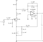
Amp in plastic box, in sim:
For positive voltage peaks, J5's or J6's gate-source junction would go in forward conduction, for negative voltage peaks in avalanche breakthrough. PN junctions can usually handle far less current in avalanche breakthrough than in forward conduction, so two extra diodes with their anodes to the sources (if the source DC bias voltage is low enough) or to ground and their cathodes to the inputs should make the circuit less vulnerable. Of course when the peaks are big enough, they will still damage things.
That's a nice design of receiver. I'm yet to be convinced that the symmetrical balance is needed but it looks like a good idea.
That design wasn't intended for VLF, which might become clear when considering the impedance of the trifilar wound RF OT (L3, L4, L6). As mentioned it was intended for ~500k to 120 MHz in order to discover the sourced of the EMI. When noticing the EMI issue could be tackled with MW only, I exchanged the amp with one, using far less supply current. One stage with single gate mosfets was enough. The active dipole also led to the discovery that in this mountainous region, MW stations haven EM field with horizontally polarized component.
Had a look for low noise JFET's intended for condenser microphones. How about 2SK596S JFET? I also found this TI JFET device the JFE150 very low noise - interesting. TI have some application notes and they give this circuit (take no notice of the crazy capacitor values) :-By the way, the simplest way I can think of to interface a ferrite rod to a computer would be to connect the ferrite rod and capacitor between gate and source of an N-channel JFET with an IDSS of about 0.5 mA, like those that are used in ordinary two-pin electret microphone capsules
Attachments
Last edited:
Thanks @richgwilliams for taking time with analysis of my recording. After hearing the result I reworked my own downconversion, targeting 516 Hz and increasing the gain. I also noted that my previous attempt was mistuned, expecting input at 17190 Hz. With these changes your .wav file and mine sound quite similar now: https://privat.bahnhof.se/wb748077/radio/2023-12-24-grimeton/
At alexander.n.se a number of ways to receive SAQ is listed: https://alexander.n.se/en/the-radio-station-saq-grimeton/lyssna-pa-saq/. Your Audacity downconversion method can become an interesting addition!
At alexander.n.se a number of ways to receive SAQ is listed: https://alexander.n.se/en/the-radio-station-saq-grimeton/lyssna-pa-saq/. Your Audacity downconversion method can become an interesting addition!
In a low noise environment where every dB counts, inverting amps at the input are a no no.
This got me thinking very carefully about OpAmps. The inverting input no no is not something I believed previously but I see what you mean.
That said, both inverting and non inverting inputs (for most OpAmps) are functionally the same. The dual input characteristic of OpAmps is their strength. So many applications rely on the "special properties" at the inverting input of an OpAmp. In fact checking what's happening at the inverting input is often a way to see how the OpAmp is behaving, because the inverting input is a "virtual earth" whatever current flows to the inverting input must cancel to zero. Usually its the feedback current cancelling the input current.
I think its possible to show that noise problems reduced at one input just transform to the other input. As an example lets consider resistor Johnson noise. If you feed input to the non inverting input ok you avoid a noisy resistor but alas the noise still goes into the inverting input from the feedback and ground resistors.
Then there are applications that totally rely on the inverting input such as a DAC where current out of the DAC is fed directly into the inverting input (no resistor) and is exactly balanced by a feedback resistor and is then output from the OpAmp as a voltage. There are many sensors that output current not voltage and are conventionally fed into the inverting input of an OpAmp. Examples are 4-20mA current loop, photocells, photomultiplier tubes, DAC's already mentioned and a few others.
Referring back to your original TL074 circuit that fed both ends of the tuned circuit into the non-inverting inputs of two OpAmps well you still had the two 100K resistors to ground and they would have been feeding noise into the non-inverting inputs just the same as my 200K input resistor.
A kind of compromise general rule comes to mind - if measuring current as input use the inverting input, if measuring voltage as input use the non-inverting input..
If anyone really wants an OpAmp that is truly low noise, very low distortion and is happy at high frequencies (over 200MHz) go for the AD8021. The datasheet is very good and I'm attaching it.
Attachments
Last edited:
- Home
- Amplifiers
- Solid State
- Tuned Sound Amplifier/Receiver for the VLF Christmas Eve transmission from SAQ, Grimeton, Sweden