The AD831 mixer in that DC receiver I'm working on claims to go down to DC, so if the frequency synthesizer can go down to 17 KHz, I'm there.
Antenna is another story. What are they using at the transmitter? At only 80 kw, it better be good.
On my end, at the house I'll be at, the end fed wire is really poor below the broadcast band. I can't find that I have a VLF loop for my loop antenna setup. So I'm thinking that a ferrite rod pulled from a transistor radio and resonated at 17 KHz might be my best bet. Maybe couple the random wire antenna into that.
Not holding out much hope of hearing it here in the south central USA.
Win W5JAG

As time is approaching and its a busy time of year I have decided to construct this simple circuit:-

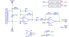
The Ferrite Rod is wound to resonate with the 8n2 COG capacitor at 17.2 KHz, U1A provides an initial gain of x2 with an input resistance of 200K. U1B gives a variable gain from x1 to x21. Power is from two Lithium batteries. No on/off switch is shown but can be included. The Antenna and Earth (Ground Earth) connections are optional. Sound output and screen to be connected to Mobile Phone, Tab or Laptop PC by 3.5mm Jack Plug.
The Ferrite Rod is wound to resonate with the 8n2 COG capacitor at 17.2 KHz, U1A provides an initial gain of x2 with an input resistance of 200K. U1B gives a variable gain from x1 to x21. Power is from two Lithium batteries. No on/off switch is shown but can be included. The Antenna and Earth (Ground Earth) connections are optional. Sound output and screen to be connected to Mobile Phone, Tab or Laptop PC by 3.5mm Jack Plug.
Attachments
Last edited:
Earth is a major issue with short wire and active (electric field) antennas. While some 40 years ago in Belgium I could use the water tubing as "ground", that only went well because it was copper tubing, stretching for miles. So a down transformer connected between "10m wire in a tree" and that ground worked very well, with computers, telex printers etc. running. In Panama that's completely different, plastic tubing, and resistance between 2m earthing rods spaced 2m is 140 ohms (!). I discovered that because the active whip (photo) didn't work as expected. I had to install common mode chokes of ~1 mH to get it to work properly.

Your input stage produces unnecessary amounts of noies: LM358 is one of the worst op-amps available on the market. And you would better use a non-inverting input amp configaration, with a feedback network with lower impedance set to a high gain of 100x for instance.As time is approaching and its a busy time of year I have decided to construct this simple circuit:-
View attachment 1249102
The Ferrite Rod is wound to resonate with the 8n2 COG capacitor at 17.2 KHz, U1A provides an initial gain of x2 with an input resistance of 200K. U1B gives a variable gain from x1 to x21. Power is from two Lithium batteries. No on/off switch is shown but can be included. The Antenna and Earth (Ground Earth) connections are optional. Sound output and screen to be connected to Mobile Phone, Tab or Laptop PC by 3.5mm Jack Plug.
LM358 is one of the worst op-amps available on the market.
With respect - RUBBISH
Agreed with bucks bunny. LM358 is the dual version of the LM324 fuzzbox. 😉
A bipolar transistor or JFET would work well.
Ed
A bipolar transistor or JFET would work well.
Ed
When using asymmetric input (antenna wire, resonant LC +(good!) ground), a jfet as source follower does the job already, Low noise, high Z and also less work piecing it together.
Interesting my thinking (very simplistic) goes as follows:-Earth is a major issue with short wire and active (electric field) antennas.
There seem to be three basic ways to receive VLF as follows:-
1. Using a Ferrite Rod that concentrates the magnetic flux variation caused by the passage of the EM wave. In this instance the circuit can be entirely floating with no reference to earth potential.
2. A conventional VLF antenna that references between earth potential and the antenna element, In this case the antenna is responding to the EM wave.
3. Using two earth electrodes some considerable distance apart (say 100m) and measuring the potential difference between them. In this instance the electric field component of the EM wave is inducing an electrical potential gradient in the earth as it passes by.
So option 1, is sensing the magnetic field component of the EM wave. Option 2. is sensing the EM wave (probably its electric field component. Option 3. is sensing the electrical field component of the EM wave as it induces eddy currents in the ground.
With respect - RUBBISH the LM358 dual OpAmp is ubiquitous throughout industry. Even Bosch use them in their range of professional power tool chargers. It is produced by at least TI, OnSemi and ST.LM358 is the dual version of the LM324 fuzzbox.
They also have at least one very useful feature, their common mode range extends below ground so ideal for current sensing applications.
In the UK the DIP version, LM358AP can be bought for 18 pence each.
Last edited:
When taking WL into account, VLF signals are only vertically polarized (horizontal component absorbed by ground) and any wire used functions as short vertical antenna. For transmitting purposes, the capacity (wire-ground) can be used to resonate a high-Q coil, and the current flowing through that series resonant circuit is what radiates. For horizontal polarization to be useful, antenna height above (good) ground has to be at least 0.05 WL. Wire used as receiving antenna is tuned via parallel resonance, to get maximum voltage. So all effective VLF receiving antennas are vertically polarized, even when the wire is hanging horizontally.Interesting my thinking (very simplistic) goes as follows:-
There seem to be three basic ways to receive VLF as follows:-
1. Using a Ferrite Rod that concentrates the magnetic flux variation caused by the passage of the EM wave. In this instance the circuit can be entirely floating with no reference to earth potential.
2. A conventional VLF antenna that references between earth potential and the antenna element, In this case the antenna is responding to the EM wave.
3. Using two earth electrodes some considerable distance apart (say 100m) and measuring the potential difference between them. In this instance the electric field component of the EM wave is inducing an electrical potential gradient in the earth as it passes by.
So option 1, is sensing the magnetic field component of the EM wave. Option 2. is sensing the EM wave (probably its electric field component. Option 3. is sensing the electrical field component of the EM wave as it induces eddy currents in the ground.
You are wrong because I want to define the input resistance seen by the Ferrite Rod tuned circuit accurately, and thus it is defined as 200K. This input resistance sets the Q of the resonant circuit.you would better use a non-inverting input amp configaration, with a feedback network with lower impedance set to a high gain of 100x for instance.
I don't want and I don't need 100x gain up front, a gain of 470/200 = 2.35 is fine, it is then followed by a variable gain of x1 to x21, then there is the gain of the Laptop sound input and later on software processing.
Believe me this circuit is very carefully thought out and you will not find a way to fault it.
Attachments

Last edited:
Here we are not talking about Bosch Tools but low noise audio application. With all respect, this input stage has at least 3 design flaws that degrade noise performance substantially. I see your post in between, You do not have the faintest clue of low noise audio design and insist on doing wrong everything - I am out here. Good luck!
With respect - RUBBISH As I use the LM358 in this application, there will be no crossover distortion. My maximum gain bandwidth product is 17200 x 21 which is 361200 well below the LM358 specification. Don't forget my intended application ie "Tuned Sound Amplifier/Receiver for the VLF Christmas Eve transmission from SAQ, Grimeton, Sweden" and the message from the Alexanderson Alternator is in Morse code not HiFi.LM358 has its uses, but audio is not one of them.
Seems to me that all criticisms of the LM358 are coming from USA members?
In a low noise environment where every dB counts, inverting amps at the input are a no no. The reason why 40 dB amplification works here is the tuned input LC: selective enough to ignore the effect of adjacent channels while also providing a limiting function in the case of strong interference (lightning).
Low noise is pointless the signal to noise ratio of the received signal is very bad. Its affected by global lightning storms that never stop. Resonating and narrow bandpass filtering around 17200 Hz is my only way of removing noise.Here we are not talking about Bosch Tools but low noise audio application. With all respect, this input stage has at least 3 design flaws that degrade noise performance substantially. I see your post in between, You do not have the faintest clue of low noise audio design and insist on doing wrong everything - I am out here. Good luck!
I really don't see the design flaws you refer to, each component choice is governed and constrained by functional objective factors. Changing the OpAmp will make absolutely no difference to performance.
Seems to me that all criticisms of the LM358 are coming from USA members?
Not at all, I'm Dutch and I also regard it as a very poor op-amp. I don't see what nationality has to do with op-amp performance anyway.
For this design the LM358 is perfect especially as they only cost GBP 0.18 each. Above all design constraints the big one is "KEEP IT SIMPLE, KEEP IT SAFE"Not at all, I'm Dutch and I also regard it as a very poor op-amp.
Intention is to propose a simple low cost design that anyone anywhere can construct.
Any OpAmp/resistor noise energy in that precise very narrow band around 17200 Hz will be very small.
Last edited:
VLF receiving antennas deliver small signals which are likely to drown in the noise of any inverting-mode opamp with 200k input resistor. It's quite likely the reception will improve when decimating that value, despite the increased damping. Easy to verify now, as there are plenty VLF stations active 24/7.
- Home
- Amplifiers
- Solid State
- Tuned Sound Amplifier/Receiver for the VLF Christmas Eve transmission from SAQ, Grimeton, Sweden