
It's best when making the holes using these cutters if you use a drill press, if available. If drilling with a hand tool, clamp the top plate to a scrap piece of wood. The wood will help to keep the drill from wandering. Use some sort of oil or other lubricant on the drill bit.
S.
S.
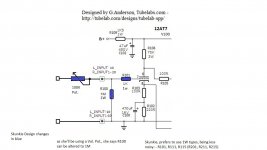
Why would one use such high value resistor for R100? Would not make it more susceptible to noise?Just to add the changes that Skunkie Designs will be using
That's what the lady said. I won't argue with her knowledge....😉Why would one use such high value resistor for R100? Would not make it more susceptible to noise?
I guess 1Meg is used as a safety grid leak in case the volume pot fails. Is that is the case then yes, 1Meg makes sense.That's what the lady said. I won't argue with her knowledge....😉
Calpe,
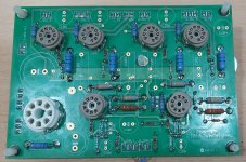
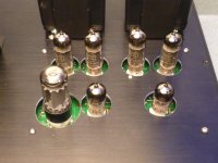
Is that a picture of your board? My preference would have been to not assemble parts to the board until you have made all the holes in the chassis top plate. With nothing on the board it's easier to use it as a layout tool.
S.
Is that a picture of your board? My preference would have been to not assemble parts to the board until you have made all the holes in the chassis top plate. With nothing on the board it's easier to use it as a layout tool.
S.
Its all under control, thanksCalpe,
Is that a picture of your board? My preference would have been to not assemble parts to the board until you have made all the holes in the chassis top plate. With nothing on the board it's easier to use it as a layout tool.
S.
Attachments
Can someone please verify the value of C2?
Tubelabs part list says
http://tubelab.com/designs/tubelab-spp/parts-list/
C2 = 150uF 450V electrolytic - DigiKey p/no. P10160-ND (no longer manufactured).
Some circuits i've seen shows C2 as a 250uF 450V
Thanks 👍
Tubelabs part list says
http://tubelab.com/designs/tubelab-spp/parts-list/
C2 = 150uF 450V electrolytic - DigiKey p/no. P10160-ND (no longer manufactured).
Some circuits i've seen shows C2 as a 250uF 450V
Thanks 👍
C2 can be 150 to 250uF. As long as you get the lead spacing correct (10mm) and the voltage rating high enough, it's not totally critical. Within reason.
C1 is the one you need to pay close attention to. Too much capacitance & you will have a very unhappy rectifier tube!
https://www.digikey.com/en/products/detail/rubycon/450USG150MEFCSN22X35/3565067
https://www.digikey.com/en/products/detail/nichicon/LGN2W181MELA35/2540500
Will work fine
C1 is the one you need to pay close attention to. Too much capacitance & you will have a very unhappy rectifier tube!
https://www.digikey.com/en/products/detail/rubycon/450USG150MEFCSN22X35/3565067
https://www.digikey.com/en/products/detail/nichicon/LGN2W181MELA35/2540500
Will work fine
Thanks for reply, but where does it say what you've mentioned above?C2 can be 150 to 250uF. As long as you get the lead spacing correct (10mm) and the voltage rating high enough, it's not totally critical. Within reason.
C1 is the one you need to pay close attention to. Too much capacitance & you will have a very unhappy rectifier tube!
https://www.digikey.com/en/products/detail/rubycon/450USG150MEFCSN22X35/3565067
https://www.digikey.com/en/products/detail/nichicon/LGN2W181MELA35/2540500
Will work fine
In the designers web site i cant see any mention that C2 value can be from 150uF up to 250uF?
http://tubelab.com/designs/tubelab-spp/
http://tubelab.com/designs/tubelab-spp/manual/capacitors/
C1 should be 47uF 450V. Having too much would do what to the rectifier Valve?
Too high a value sends the GZ34/5AR4 to the heaven.C1 should be 47uF 450V. Having too much would do what to the rectifier Valve?
A maximum value of 60µF is specified in the data sheet.
Attachments
Calpe,
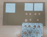
Does your paper template exactly match the board? Some printers might stretch or crunch it a bit. Even if you use M4 screws in the 5mm board holes you don't have to be out much before you have to start filing holes. Just sayin' from someone who has been there.
S.
Does your paper template exactly match the board? Some printers might stretch or crunch it a bit. Even if you use M4 screws in the 5mm board holes you don't have to be out much before you have to start filing holes. Just sayin' from someone who has been there.
S.
Thanks guys for your valuable inputs, yet again.Calpe,
Does your paper template exactly match the board? Some printers might stretch or crunch it a bit. Even if you use M4 screws in the 5mm board holes you don't have to be out much before you have to start filing holes. Just sayin' from someone who has been there.
S.
Yes, i was very careful about printing the PDF PCB layout and it matches 100%.
If i'm not mistaken the Tubelab Simple PP designer George Anderson mentioned it in his write up.
George did mention it. If you are using the grommets I've used to dress up the holes for the tubes you will obviously need larger holes. Some of the holes will get very close together. Be sure you locate them as accurately as possible. Even then some of the grommets will need to be trimmed a bit and one will need a bit of a radius cut out to clear the screw near the centre of the board.
Attachments
Might George Anderson, the Tubelab Simple PP designer might have the voltages to expect at each Valve pin on the original build?
e.g.
Also expected B+ voltage?
V1 = pin 8
V100 = pins 1, 2, 3, 6, 7, 8
V101 = pins 2, 3, 7, 9
V102 = pins 2, 3, 7, 9
e.g.
Also expected B+ voltage?
V1 = pin 8
V100 = pins 1, 2, 3, 6, 7, 8
V101 = pins 2, 3, 7, 9
V102 = pins 2, 3, 7, 9
Much will depend on what voltage you have on pin 8 of V1. This depends, to a great degree, on your power transformer.
The plates and screen grids of the EL84s will be a handful of volts less than what's on the CT of the OP trans. The EL84 cathodes will likely be around 10 to 12 volts or so.
S.
The plates and screen grids of the EL84s will be a handful of volts less than what's on the CT of the OP trans. The EL84 cathodes will likely be around 10 to 12 volts or so.
S.
Yes, C2 can be whatever you can fit into the board, or off board as need be. Anything below 100uF may cause hum, and I would go to at least 150 uF in a 50 Hz country. Going beyond 250 uF or so rarely offers any benefit though.Thanks for reply, but where does it say what you've mentioned above?
In the designers web site i cant see any mention that C2 value can be from 150uF up to 250uF?
http://tubelab.com/designs/tubelab-spp/
http://tubelab.com/designs/tubelab-spp/manual/capacitors/
C1 should be 47uF 450V. Having too much would do what to the rectifier Valve?
Every rectifier tube has a maximum peak current spec. This along with the total DC resistance in the transformer secondary determines the maximum capacitance. Sometimes a tube manufacturer will specify a maximum capacitance. GE calls for 3.7 amps peak, while Amperex calls for 60 uF max. 47 uF is a good limit for today's less than stellar tube quality. Exceed this and your tube may arc over internally which generally kills the tube, and possibly other parts.
Might George Anderson, the Tubelab Simple PP designer might have the voltages to expect at each Valve pin on the original build?
e.g.
Also expected B+ voltage?
The voltages depend greatly on the tubes and transformers used in the build. I have one amp that has a B+ of 430 volts and another that runs about 330 volts. Swapping in a different set of output tubes, or a different rectifier can change the voltages by 10 volts or more.
- Home
- Amplifiers
- Tubes / Valves
- Tubelab SPP first timer build