Stonegreen, thanks for that info.For example:
Inrush Current Limiter: (ICL) 235-1349-ND
Ceramic Capacitor: 490-17655-1-ND - (CT) / 490-17655-3-ND - (TB)
Film Capacitor´: 4499-MKS2F031001E00JSSD-ND
Through Hole Resistor: PPC5W10.0CT-ND - (CT) / PPC5W10.0TB-ND - (TB)
These parts were described by 'wall of sound', and 'see also here'
Were these parts used in the original Tubelab build http://tubelab.com/designs/tubelab-spp/ ?
I think fitting 2 diodes HER108's (J. Broskie mod.) between mains tx's secondary winding and the rectifier Valve 5AR4 (pins 4 & 6), allows the Valves to reach cathode emission before they get the full B+
Last edited:
The parts mentioned were not used on Tubelabs, only on 'Wall Of Sound'.
If you're using a metal case, you should also ground it. The CL90 serves as a switch-on delay so that the fuse does not always blow.
Perhaps Steve or George should say something about whether these things are necessary.
If you're using a metal case, you should also ground it. The CL90 serves as a switch-on delay so that the fuse does not always blow.
Perhaps Steve or George should say something about whether these things are necessary.
Goerge reported earlier, or perhaps it was a different thread, that the diodes between the trans secondary and the rectifier aren't really necessary with the SPP because the GZ34 isn't stressed much by the SPP.
The CL90 is optional, I just like to use one so it's a little easier on the tubes until things warm up a bit.
The paralleled resistor and cap between circuit ground and chassis ground is a thing I picked up from Broskie. Again, not absolutely necessary but I like to have it.
I used the IRL and the cap/resistor mentioned above on the WoS SPP build and it all worked out fine.
Your choice whether or not you want to or not.
Attached are pictures of an old Fisher 20-A mono amp I rebuilt (actually a pair). I changed them over to the SPP circuit. I added more capacitor nodes in the B+ supply for more filtering and to drop the voltage. I also added two, 0.05 ohm resistors in the filament supply to prevent over-voltage. I didn't use IRLs in these. And they sound? Great. Originally, I had NOS PIO coupling caps but the amps sounded too slow and not resolving of detail. I switched the PIOs out for the Obligatos you see in the picture. Much more detailed sound but still smooth in the highs.
S.
https://wallofsound.ca/audioreviews/amplification/ace-steve-update-4-i-should-have-known-better/
Attachments
Thanks again Stonegreen.The parts mentioned were not used on Tubelabs, only on 'Wall Of Sound'.
If you're using a metal case, you should also ground it. The CL90 serves as a switch-on delay so that the fuse does not always blow.
Perhaps Steve or George should say something about whether these things are necessary.
I can appreciate that the Inrush current limiter 120 Ohms ±25% 2 A is just for that to prevent a surge on switch on.
But if the i/p fuse was the correct value there would be no problem of the fuse blowing.
My case will be metal and so the case will be 'earthed' direct to the mains i/p socket.
As we know the specific cable colour for protective earth cables is green/yellow striped.
Perhaps if the designer, George of http://tubelab.com/designs/tubelab-spp/ can enlightened us of the amps value for the mains i/p fuse.
The topic of fuse for the SPP has already been discussed here:
https://www.diyaudio.com/community/threads/easy-diy-tube-amp.384618/post-7000607
At 230VAC, 1A or 1A6 should be sufficient (slow-blow fuse).
https://www.diyaudio.com/community/threads/easy-diy-tube-amp.384618/post-7000607
At 230VAC, 1A or 1A6 should be sufficient (slow-blow fuse).
The IRL isn't really about the fuse blowing. It's about a slower ramp-up of voltage to the power transformer primary and thus a slower ramp-up of AC to the filaments and DC to the rest of the circuit. The IRL is your choice. I like the possibility that it might help extend tube life.
S.
S.

Thanks for reply, though it appears very much up in the air in that thread about the value, but in post 152, a 3A appears to be fine😉The topic of fuse for the SPP has already been discussed here:
https://www.diyaudio.com/community/threads/easy-diy-tube-amp.384618/post-7000607
At 230VAC, 1A or 1A6 should be sufficient (slow-blow fuse).
A little surprised that Tubelab the designer http://tubelab.com/designs/tubelab-spp/ appears to have no reference of a value.
Unless of course when his web site was hacked that information was removed.....
Last edited:
I always order extra resistors and other small/cheap passives in case I screw up while building 🙂
Yup - I normally order one more mosfet/reg and depending on the price 10 of the passives.
An example was the 3080 through hole.. those have disappeared. Now I want some more and I have the choice of SMT or SMT..
The value of the fuse depends on the supply voltage, 110V or 230V.
The transformer for the SPP should provide about 200 watts, roughly estimated.
At 110V it would be ~2A and at 230V ~1A. The next larger value is then 3A and 1A6.
I would order these values in sufficient quantity.
The transformer for the SPP should provide about 200 watts, roughly estimated.
At 110V it would be ~2A and at 230V ~1A. The next larger value is then 3A and 1A6.
I would order these values in sufficient quantity.
Interesting read https://www.diyaudio.com/community/...ect-primary-secondary-windings-please.349527/The value of the fuse depends on the supply voltage, 110V or 230V.
The transformer for the SPP should provide about 200 watts, roughly estimated.
At 110V it would be ~2A and at 230V ~1A. The next larger value is then 3A and 1A6.
I would order these values in sufficient quantity.
Posts 1-3...
Should be arriving any time now...Calpe,
Did you get your transformers and choke yet?
Now extremely delayed, too many factors setting me back.
I've chased up Primary Winding today about my Mains Tx, the PushPull o/p Tx's and the choke (replacing R1), there was a lead time of 4 weeks, but i thought i'd ask them anyway.
The case i'm probably going for the R.S. Components RS PRO, 2U 19-Inch Rack Mount Case Ventilated, 482.6 x 88.1 x 245mm - Stock No.: 665-7719, decided on it as i used one some years back with my Elektor Pre-Amplifier, weighing up its total cost, delivered, which was favourable.
I've cut out a thin piece of cardboard 482.6 x 245 and then using cut pieces of paper of the sizes of the transformers and the printed pdf of the Tubelab PCB all looks good.
Just need to sort out the correct PCB spacers, screws, nuts, washers etc.
The PCB holes are approx. 5mm and the outer diameter is approx. 10mm.
Would prefer using black screws etc,, but it's not that straight forward.
Also deciding whether to get some MiliOhm resistors in case the AC Mains supply pushes the secondary filament voltages above 6.3.
Probably better to be safe than sorry.
I'm just a couple of steps away from ordering all the parts but I'm really not sure about using the components in post #179, posted by Stonegreen.
Inrush Current Limiter: (ICL) 235-1349-ND
Ceramic Capacitor: 490-17655-1-ND - (CT) / 490-17655-3-ND - (TB)
Film Capacitor´: 4499-MKS2F031001E00JSSD-ND
Through Hole Resistor: PPC5W10.0CT-ND - (CT) / PPC5W10.0TB-ND - (TB)
Where exactly do these components go electrically? It doesn't appear to be very clear.
I really would appreciate some detailed information about all these?
Thanks again for your support.
Last edited:
Primary Winding UK will be sending over to me my Mains Tx, Push-Pull Output Tx's and choke next Wednesday, so i should have them by next weekend.😎
The use of the mentioned components was described at 'WallOfSound'.
There are several documents that deal with the manufacture and commissioning of the Tubelabs SPP.
Attached is a simple circuit diagram for local use of the components.
There are even better solutions for wiring the LED.
All parts are optional.

There are several documents that deal with the manufacture and commissioning of the Tubelabs SPP.
Attached is a simple circuit diagram for local use of the components.
There are even better solutions for wiring the LED.
All parts are optional.
The reason for the two 100R resistors in the WOS instructions is a bit obscure. If you look closely at many LEDs, one of the leads inside the molded plastic housing, is very close to the surface. If this should get shorted to the chassis one of the resistors should act like a fuse, maybe, hopefully. This is especially important in amps like the SPP where the filament voltage is "floated" at several volts above circuit ground. At least that's my reasoning. I'm sure some might take issue with this.
S.
S.
All parts (nearly) now ordered, a couple of items coming via AliExpress due to their favourable prices and free shipping.
I must admit i'm still at a loss with regards to the size of Aluminium StandOff's, screws, nuts, washers and locking washers.
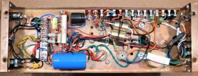
The PCB will hang under the top cover, with holes drilled for the Valves, so they'll be in full view and glowing.
The Transformers will also sit on the top cover in full view, keeping the Mains Tx away from the Push-Pull O/P Tx's.
Hanging the PCB......
The PCB (5) holes measures 5 mm in diameter, but of course the actual diameter of the complete outer area is 10mm, as shown in image, which will give full support for the PCB.
I'm looking at https://www.aliexpress.com/wholesal...Text=standoff+spacer&spm=a2g0o.home.1000002.0 as the prices are much better.

My problem is trying to work out which Standoff to get.
Allowing for Thread Size - Body Length - Overall Length - External Width.
Will i need M4 (4mm) or M5 (5mm)?
I know that most of you, especially Stefe in Skunkie Designs and not doubt George, the designer of the SPP Valve Amp, would probably have 6 units up and running in the time i'm taking!
I must admit i'm still at a loss with regards to the size of Aluminium StandOff's, screws, nuts, washers and locking washers.
The PCB will hang under the top cover, with holes drilled for the Valves, so they'll be in full view and glowing.
The Transformers will also sit on the top cover in full view, keeping the Mains Tx away from the Push-Pull O/P Tx's.
Hanging the PCB......
The PCB (5) holes measures 5 mm in diameter, but of course the actual diameter of the complete outer area is 10mm, as shown in image, which will give full support for the PCB.
I'm looking at https://www.aliexpress.com/wholesal...Text=standoff+spacer&spm=a2g0o.home.1000002.0 as the prices are much better.
My problem is trying to work out which Standoff to get.
Allowing for Thread Size - Body Length - Overall Length - External Width.
Will i need M4 (4mm) or M5 (5mm)?
I know that most of you, especially Stefe in Skunkie Designs and not doubt George, the designer of the SPP Valve Amp, would probably have 6 units up and running in the time i'm taking!
Last edited:
Calpe,
If you build it like the WOS article with parts on both sides, I suggest you use M4 x 20mm long standoffs. This will give you some play, a good thing, within the board's 5mm holes. What you have to be watchful of is the height of C2, the large electrolytic cap. Make sure the cap you order will fit in your chassis. If you mount the PS choke in the chassis watch its height too. Or order a chassis to suit.
S.
Thanks Stonegreen and Steve for your valuable input again.Calpe,
If you build it like the WOS article with parts on both sides, I suggest you use M4 x 20mm long standoffs. This will give you some play, a good thing, within the board's 5mm holes. What you have to be watchful of is the height of C2, the large electrolytic cap. Make sure the cap you order will fit in your chassis. If you mount the PS choke in the chassis watch its height too. Or order a chassis to suit.
S.
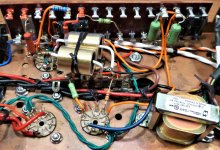
C2 as per Tubelab BOM is a 150uF 450V electrolytic, DigiKey P/No. P10160-ND
It's height being 1.181" (30.00mm), but it's no longer available (i won't bore you with its other characteristics) so i chose another one having 32mm height, diameter is fine.
My case is a 2U - 482.6 x 88.1 x 245mm, so i've got enough height (88.1mm).
From what will be the bottom (up side down) C2 to the top chassis case there is a space of 52mm.
The standoff's i'd like to get would be aluminum/brass, due to the area warmth, now ordered via AliExpress.
Last edited:
- Home
- Amplifiers
- Tubes / Valves
- Tubelab SPP first timer build