Sorry, but that's a no, to thatCalpe,
I've used the remote volume much like these before and they worked OK, The only problem is finding 9 to 12 volts in a SPP build. The filaments are only 6 volts. Unless you are really set on remote, just get a 50K or 100K Alps Blue Velvet pot (same as in the picture in your link but no motor, board or any of the other bits) https://www.ebay.com/itm/272249742734?hash=item3f6359658e:g:vXMAAOSwU1FXP-Fb.
I will be using a normal type of Volume control pot.I needed 5VDC for the Khozmo attenuators w/remote and used a small SIMPS tucked into a corner of the preamp chassis. Works well but takes up a little space.

How did we get the idea you were looking for a remote volume control and needed a low voltage supply? Sorry for the diversion! 😳
I guess I caused the distraction when I wrote that “I’m eyeing one of those” in post #137 in response to OP’s inquiry about attenuators. Apologies.
No harm done, thanks for the input anywayHow did we get the idea you were looking for a remote volume control and needed a low voltage supply? Sorry for the diversion! 😳
Apologies not needed, thanks for the input anywayI guess I caused the distraction when I wrote that “I’m eyeing one of those” in post #137 in response to OP’s inquiry about attenuators. Apologies.
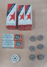
Collecting my Valves & valve sockets today, the buzz is still there.
Transformers & Choke should arrive in a few weeks from https://primarywindings.com/
Transformers & Choke should arrive in a few weeks from https://primarywindings.com/
Looking for some advise about fitting the Valve sockets?
My build is to have the Valves displayed and coming through the top cover of a case.
Of course i don't want them to appear like Leaning Towers of Pisa or at different heights.
Yes, the Valves are of course different heights
1x 5AR4
2x ECC81 (12AT7)
4x EL84
So of course i can see there will be an issue getting the Valve sockets level at the same height.
What i was thinking was to fit the 8-pin socket and to make sure it's level.
Then to fit all the 9-pin sockets so that they are all level with each other.
It's virtually impossible for example to have the 6x 9-pin B9A Belton sockets at the same height as the 1x 8-pin Octal socket.
You could place a spacer underneath each socket when you solder it in, so that each socket is the same space above the board. You're probably going to have the board upside down anyway, so use the same spacer for each valve. It could be something like a piece of cardboard or a small wooden or plastic block -- basically anything really.
Managed to view it, jcalvarez, no problems.
With both the 1x 8-pin Octal Socket and 6x 9-pin B9A Belton sockets pushed into the PCB holes, obviously the 9-pin sockets are lower.
Tubelabs says http://tubelab.com/designs/tubelab-spp/manual/sockets/
"If inverted assembly is used we want to have the surfaces of the tube sockets all in the same plane so they will be flush with the top of the mounting plate. Start with the octal socket. It is the tallest socket so it should be inserted into the PC board as far as it will go. The 9 pin miniature sockets will all be spaced slightly off the board so that they will be in line with the octal socket".
With my B9A Belton sockets it almost impossible to get them to the same height as the 8-pin socket, as the 9-pin socket pins just skimmer over the PCB holes, which would be very insecure.
I'm tempted to just fit all the sockets into the PCB allocated holes.
At the same time making sure they are all level avoiding an appearance of Leaning Towers of Pisa Valves (tubes).
Thanks. I have tried this, but the pins of the 9-pin B9A Belton sockets will need to fit through the PCB holes for stability.You could place a spacer underneath each socket when you solder it in, so that each socket is the same space above the board. You're probably going to have the board upside down anyway, so use the same spacer for each valve. It could be something like a piece of cardboard or a small wooden or plastic block -- basically anything really.
This being the case the 6x 9-pin B9A Belton sockets will actually be lower than the 1x 8-pin Octal Socket.
I suppose that as long as the 6x 9-pin B9A Belton sockets, soldered in place, level and stable, that this should be fine??
Clearly not 100% of the 12AT7 and EL84 will be viewable.
I can't see another way out.
I meant just a temporary spacer, to consistently set the height so that you don’t need to press the sockets in the whole way. Certainly they should make good connection, but if there are a few mm between fully inserted and not, then you can use a spacer to make them all a consistent height.
if that’s important. Personally I would notice it for the first 10 minutes and then would forget about it completely.
if that’s important. Personally I would notice it for the first 10 minutes and then would forget about it completely.
Just a note to say I'm waiting for the transformers to arrive.
I'm away on leave for 2 weeks as from Wednesday, so sadly things have got grounded.
Once back ill finish off the parts & case order.
Speak soon.
I'm away on leave for 2 weeks as from Wednesday, so sadly things have got grounded.
Once back ill finish off the parts & case order.
Speak soon.
Compared to getting the chassis right, the process of assembling the PCB is trivial. It is worth getting a couple of hole punches for the tube socket holse for the top cover/plate. I went to Rapid Online in the UK - they were pretty cheap there - but Etsy is another option (although my only order there never arrived and they had to refund).
This one would do the octal socket, although some octal sockets are 1 1/8". For £12 it makes for a professional finish.
1" hole punch
It is worth using a drawing package to get all the dimensions correct for the case, and optimising the placing of the parts so hot items are not too close to other items, and transformers are correctly orientated. Last time I covered the whole case in masking tape, marked it all up, and drilled through the tape so prevent damage to the surface. A simple amp necessitated a lot of time consuming drilling (fuse, IEC socket, speaker outputs, RCA inputs, pilot light, on/off switch, volume control, transformer and choke fixing holes (16 of those!), holes for transformer and choke wires through the top plate, PCB mounting holes). Some people fit switxhes for different listening modes (triode, UL) and speaker impedances, but that can lead to complexity. Best to be prepared to flip it over and switxh wiring semi-permanently for starters, IMO.
Thank you OldHector for this valuable advise.
I too can see a lot of time will be needed to ensure things are marked, drilled correctly.
I too can see a lot of time will be needed to ensure things are marked, drilled correctly.
You might find my write up useful and the attached BOM for mouser, that I updated as I built the amp. I’m based in Europe so everything was sourced from European suppliers.Thank you OldHector for this valuable advise.
I too can see a lot of time will be needed to ensure things are marked, drilled correctly.
https://www.diyaudio.com/community/threads/tubelab-simple-p-p.148694/page-39#post-6839693
im just coming back to this after almost a year. I’ve finished and plan to turn it on for the first time this week and test it.
- Home
- Amplifiers
- Tubes / Valves
- Tubelab SPP first timer build